
90-DEGREE HYBRID COUPLER
The even and odd mode characteristic impedances, respectively denoted by Z0e and Z0d, of the slot-coupled line are5
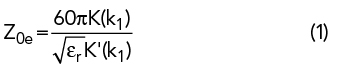

where K(k) is an elliptical integral of the first kind and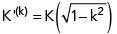 .
.
The parameters k1 and k2 are calculated from
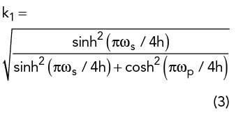
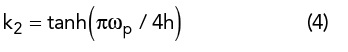
where h is thickness of substrate, ωp is the width of the top and bottom equivalent microstrip patches and ωs is the width of the equivalent rectangular slot. Their relationships with the actual dimensions (see Figure 3c) are
Using equations 1 through 7, the initial dimensions Dm, DS and DL were determined and then optimized using ANSYS software. For the 90-degree hybrid coupler, the optimized dimensions were Dm=6, DS=8 and DL=12.8 mm. The simulated performance of the hybrid coupler is shown in Figure 4.
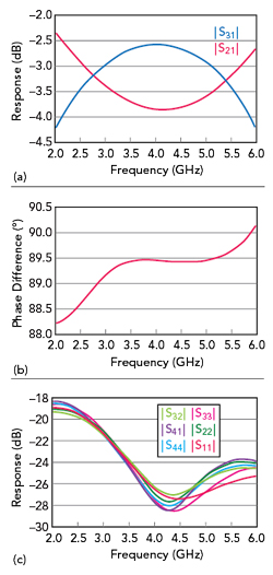
Figure 4 Simulated transmission (a), phase (b), isolation and reflection (c) characteristics of the 90-degree hybrid coupler.
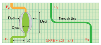
Figure 5 Phase shifter structure.
PHASE SHIFTERS
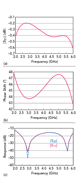
Figure 6 Simulated transmission (a), phase (b) and reflection (c) characteristics of the 45-degree phase shifter.
The phase shifter shown in Figure 2b can be viewed as the hybrid coupler in Figure 2a with two ports terminated by open circuit impedances. Its phase shift is6

where βef = β0 √(εr), βm is the corresponding microstrip propagation constant, l=λm/4, λm is the effective microstrip wavelength and lm is the microstrip line reference length. Δφ is the phase difference between two transmission paths (see Figure 5).
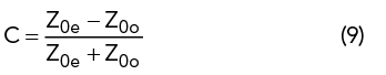
Equation 8 shows there are two degrees of freedom to achieve the desired phase shift: the coupling coefficient C and lm. In actual application, lm must be calibrated with a phase-compensated microstrip line. Thus, the phase shift Δφ is determined only by C, and its value is inversely proportional to C. C is defined by Z0e and Z0o as
Equations 1 through 9 define the relationships between the phase shift Δφ and the dimensions Dm, DS and DL. Three new variables Dpmi, DpSi and DpLi (see Figure 5) are used for the corresponding dimensions of the phase shifters, distinguishing them from those of the hybrid coupler. Similarly, the initial values were calculated and then optimized using ANSYS. The optimized dimensions in mm were:
- 45-degree phase shifter: Dpm45=4.35, DpS45=7.4, DpL45=12.1
- 22-degree phase shifter: Dpm22=11.2, DpS22=13.2, DpL22=12.8
- 67.5-degree phase shifter: Dpm67=2.7, DpS67=6.2, DpL67=12.2.
The simulated performance is shown in Figures 6, 7 and 8, respectively.