

In many applications, such as balanced power amplifiers, mixers and antenna systems, power dividers/combiners are required. Power dividers using quarter-wave lines become prohibitively large at the lower frequencies and result in MMIC chips of larger size and higher cost. The lumped-element approach, which uses lumped inductors and capacitors, is one of the solutions to this problem. Inductors for microwave circuits can be realized with air-wound coils; however, such coils must be space-wound with gaps between turns resulting in wide variations in their inductance value.1 Spiral inductors represent another possible compromise, although their quality factor (Q) is often sacrificed to obtain adequate inductance. Equivalent lumped-element models for spiral inductors have been obtained from two-port S-parameter measurements. These models do not lend themselves readily to design applications because their elements are difficult to evaluate in advance.2,3,4 Gupta and Getsinger5 presented a quasi-lumped-element branch-line coupler, which uses lumped capacitors and short-circuited transmission lines as inductors, but the resulting design is inconvenient to fabricate.
In this article, a new miniaturized transmission line technique, using a shorted parallel-coupled pair instead of a microwave inductor, is introduced. It enables the lumped inductor of the power divider to be transformed into a short distributed transmission line. This technique provides flexibility in size.
The Short Coupled Line Equivalent to a Lumped Inductor
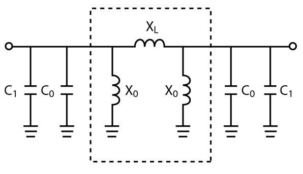
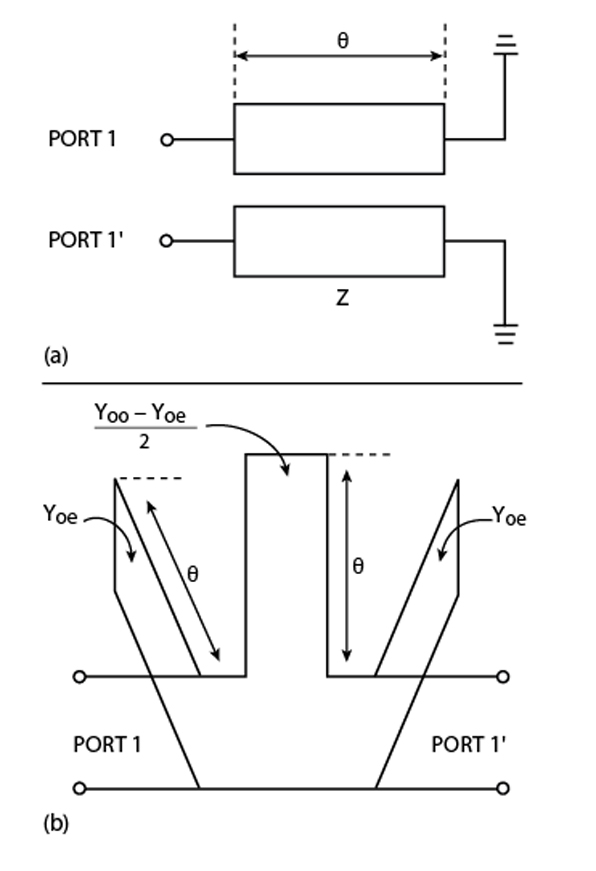
The quarter-wavelength transmission line shown in Figure 1 is a key element in power combiners. It can be equated to a combination of a lumped inductor and lumped capacitors. The aim of this study is to obtain a smaller distributed circuit that is equivalent to the lumped inductor in the quarter-wavelength transmission line. With an artificial resonance inserted, the equivalent circuit becomes the one shown in Figure 2 . Figure 3 shows a shorted parallel-coupled line and its equivalent P network, except for a 180° phase difference.6,7 The dotted box in the equivalent circuit of a  /4 transmission line can be made equal to the shorted parallel-coupled line if the following equations are satisfied:
X0 = Zoe tan  (1)
(1)
XL = {(2ZoeZoo)/(Zoe-Zoo)}tan (2)
where
X0 = shunt impedance in the  network
XL = series impedance in the network
Zoe, Zoo = even and odd impedances of the shorted parallel-coupled line
= electrical length of the shorted parallel-coupled line
 = angular frequency
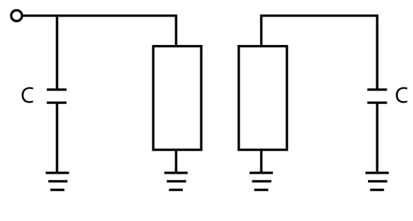
The resultant quarter-wave transmission line is shown in Figure 4 . The capacitor is expressed as
C = {(Y0 cot )/ } + {1/( Zoe tan )} (3)
where cot is inserted for XL to be equal to the impedance of C1 in the equivalent circuit of a /4 transmission line. For example, in the design of a power divider, the characteristic impedance of the /4 transmission line is XL = 70  and from Equation 2, the following relation is obtained:
Z0 = (2ZoeZoo)/(Zoe-Zoo) = XL cot (4)
where
Z0 = characteristic impedance for the shorted parallel-coupled line
As the electrical length becomes shorter, the characteristic impedance becomes larger. This trend is similar to the lumped distributed /4 transmission line in which the characteristic impedance of the shorter transmission line proposed by Hirota tends to be high.8 In this case, the higher impedance is limited to approximately 100 because the width of the high impedance line becomes too narrow to fabricate and its losses increase. Thus, the transmission line in power dividers could not be shorter than /8. Fortunately, the very high characteristic impedance Z0 is easily obtained in a coupled line.9 At this point, it becomes necessary to examine the phase variation of a /4 transmission line with frequency, compared to the shorted parallel-coupled line because the artificial resonance gives rise to a narrower band. In the equivalent circuit of a /4 transmission line composed of a shorted coupled line and capacitors, the S21 parameter of the /4 line is given by
S21 = (-y21Y0/Dy) (-1) (5)
where
 y = (y11 + Y0)(y22 + Y0) - y12y21
y11 = y22 = -j Yoe cot -j {(Yoo - Yoe)/2} cot + jB
y21 = y12 = -j {(Yoo - Yoe)/2} cot
B = Yoe cot + Y0 cot (6)
In Equation 5, the minus value in parentheses shows that there is a 180° phase difference between the network and the shorted coupled section. y11, y12, y21 and y22 are the y-parameters of the shorted coupled line with the capacitor C in the equivalent /4 transmission line circuit. At the resonance frequency, Equation 6 is satisfied when the characteristic admittance Yoe of the shorted transmission line is equal to the shunt capacitance. With a straightforward analytical manipulation, the equation for the phase of S21 can be derived as
Phase of S21 = 3 /2 + tan-1x1 + tan-1x2 (7)
where
x1 = B/Y0 -2cot - Yoecot /Y0 (8)
x2 = (B - Yoe cot )/Y0 (9)
Y0 = (Yoo - Yoe)/2
Near the center frequency, x1 and x2 are expressed by -cot and cot , respectively, using Equation 6. The phase of S21 is -90° at the resonance frequency. If the frequency deviates from the center frequency, the relation C0 = Yoe cot cannot be satisfied and the phase of S21 starts to deviate from -90°. At this point, the most important item is to decrease the frequency sensitivity of the equivalent /4 transmission line. If Yoe is small, the frequency sensitivity decreases because of the very small shunt value of C0 in the artificial resonance circuit. The coupling coefficient K is
K = (Yoo - Yoe)/(Yoo + Yoe) (10)
From Equation 10, the following relation is obtained:
Yoe = {(1-K)/(1+K)} Yoo (11)
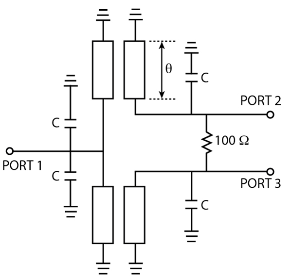
From Equation 11, when the coupling coefficient is nearly unity, Yoe is very small. The 90° phase shift near the center frequency is independent of the coupling coefficient K. As a result, the larger coupling coefficient K causes the /4 transmission line with a shorted coupled line to be broadened as a function of frequency. Figure 5 shows the final reduced size power divider with shifted coupled line instead of a lumped inductor and lumped capacitor. It is very compact and simple to fabricate.
|
Table 1 | |||||||
|
Z o = 250 |
| ||||||
|
K(dB) |
-1 |
-3 |
-5 |
-10 |
-15 |
-20 |
-25 |
|
Zoe ( |
2048.75 |
606 |
321.25 |
111 |
53.75 |
27.5 |
14.875 |
|
Zoo ( |
117.812 |
103.625 |
89.986 |
58.792 |
37.587 |
22.541 |
13.293 |
|
BW (%) |
129.9 |
110.5 |
76.7 |
40.4 |
23 |
12.9 |
7.4 |
|
Z o = 400 |
| ||||||
|
K(dB) |
-1 |
-3 |
-5 |
-10 |
-15 |
-20 |
-25 |
|
Zoe ( |
3278 |
968 |
514 |
183.8 |
86 |
44 |
23.8 |
|
Zoo ( |
188.499 |
165.753 |
143.978 |
95.779 |
60.14 |
36.066 |
21.269 |
|
BW (%) |
131.3 |
112.5 |
77.7 |
41.6 |
23.4 |
13.1 |
74 |
|
Z o = 500 |
| ||||||
|
K(dB) |
-1 |
-3 |
-5 |
-10 |
-15 |
-20 |
-25 |
|
Zoe ( |
4097.5 |
1212 |
642.5 |
222 |
107.5 |
55 |
29.75 |
|
Zoo ( |
235.624 |
207.25 |
179.922 |
117.585 |
75.175 |
45.082 |
26.586 |
|
BW (%) |
131.7 |
113.2 |
78 |
41.2 |
23.5 |
13.1 |
7.4 |
|
Z o = 700 |
| ||||||
|
K(dB) |
-1 |
-3 |
-5 |
-10 |
-15 |
-20 |
-25 |
|
Zoe ( |
5736.5 |
1694 |
899.5 |
321.65 |
150.5 |
77 |
41.65 |
|
Zoo ( |
329.873 |
290.086 |
251.961 |
167.613 |
105.245 |
63.115 |
37.221 |
|
BW (%) |
132 |
113.4 |
78.2 |
41.9 |
23.6 |
13.2 |
7.5 |
|
Z o = 1000 |
| ||||||
|
K(dB) |
-1 |
-3 |
-5 |
-10 |
-15 |
-20 |
-25 |
|
Zoe ( |
8195 |
2424 |
1285 |
444 |
215 |
110 |
59.5 |
|
Zoo ( |
471.248 |
414.501 |
359.944 |
235.169 |
150.35 |
90.164 |
53.172 |
|
BW (%) |
132.1 |
113.7 |
78.3 |
41.7 |
23.6 |
13.2 |
7.5 |
|
Z o = 2000 |
| ||||||
|
K(dB) |
-1 |
-3 |
-5 |
-10 |
-15 |
-20 |
-25 |
|
Zoe ( |
16390 |
4848 |
2570 |
888 |
430 |
220 |
119 |
|
Zoo ( |
942.496 |
829 |
719.888 |
470.339 |
300.699 |
180.328 |
106.345 |
|
BW (%) |
132.2 |
113.7 |
78.4 |
41.4 |
23.6 |
13.2 |
7.4 |
Simulation and Experimental Results
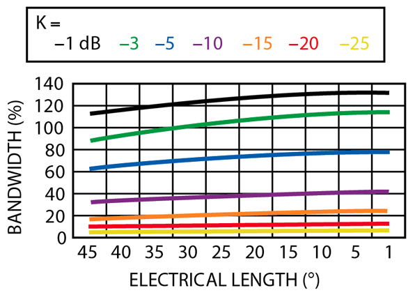
Figure 6 shows the bandwidth of the power divider as a function of the shorted transmission line length for various values of K. These simulated results were obtained using the Agilent ADS program. The bandwidth increases as the coupling coefficient K of the shorted coupled line is increased. A peculiar feature is that the bandwidth increases slightly as the electrical length decreases. This is contrary to the results shown by Hirota8, where the bandwidth of the reduced size of the /4 transmission line decreases with its size. The coupling coefficient K has a significant effect on the bandwidth of the power divider. Because of the effect of the coupling coefficient K, the bandwidth of the miniaturized is a strong function of how a tight coupling coefficient can be realized during fabrication. A broadside coupled stripline or a Lange coupler can be used for this application.
Table 1 shows Zoe, Zoo and bandwidth as a function of the coupling coefficient K and characteristic impedance Z0. Since only miniaturized transmission lines are of interest, the table considers only electrical length shorter than 15°. The results show that both Zoe and Zoo are larger as the electrical length decreases for constant coupling coefficients K.
As K increases, Zoe increases abruptly while Zoo increases slowly. Since a large coupling coefficient means a wider bandwidth, it is difficult to fabricate a power divider with smaller and wider bandwidth simultaneously.
An experimental, 1 GHz reduced-size power divider was fabricated with microstrip lines on a Teflon substrate with a permittivity  r = 3.5 and a thickness of 0.5 mm. The length of the /4 transmission line with a characteristic impedance of 70 is transformed into a /24 coupled line length with a characteristic impedance of 273 and two capacitors of 7.3 pF. It should be pointed out that, to realize the tight coupling necessary, parallel suspended coupled striplines or a Lange coupler are the best option. However, suspended striplines with broadside coupling are very hard to fabricate because of the connection of the lines and capacitors to ground. The Lange coupler needs RFIC technology to realize the tight coupling. Both approaches lead to higher costs. Since narrow band couplers are also in demand in modern communication systems, a lower coupling coefficient can be used. Therefore, K was chosen to be -10 dB using microstrip lines.
|
Table 2 | |
|
Zoe ( |
117.233 |
|
Zoo ( |
62.067 |
|
C (pF) |
7.3 |
|
L (mm) |
8.09 |
|
W (mm) |
0.3 |
|
S (mm) |
0.244 |
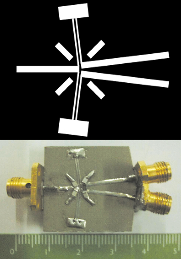
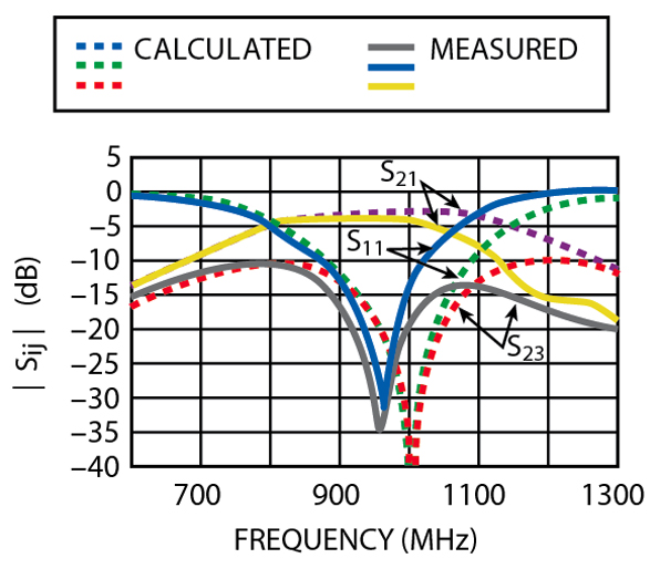
The coupled microstrip characteristics used for this case are shown in Table 2 . Figure 7 shows the layout and a photograph of the fabricated power divider. The equivalent inductance of the via-holes in the circuit was difficult to calculate and can explain the difference between simulated and experimental results.10 In order to minimize the via-hole inductance, a 0.5 mm thick microstrip substrate is used. The effect of the via-hole grounding on frequency shift was also taken into account for determining the line lengths. Commercial chip capacitors were used, although it was difficult to obtain the exact values necessitated from the simulation. Some small errors can be caused by these variations in capacitor values. The measured performance of the power divider is shown in Figure 8 .
The measured insertion and return losses are in relatively good agreement with the simulated ones. The slight frequency shift in the return and isolation losses is caused by the inaccuracy of the commercial capacitor and via-hole model. The insertion loss of -3.6 dB is due to conductor loss and the capacitor and via-hole accuracies.
Conclusion
A new method of reducing the size of a power divider, using a shorted coupled line pair instead of a lumped inductor, has been proposed and confirmed through experiments using microstrip lines at 1 GHz. The size of the quarter-wavelength transmission line has been reduced to l/24. The proposed method has the advantage of excellent design accuracy. The length of the transmission line could be reduced further, but the bandwidth becomes too narrow. To design a broad bandwidth requires a very tight coupling and is difficult to realize.
Acknowledgment
This work was supported by grant number R01-2001-00298 from the Korea Science and Engineering Foundation.
References
1. P. Vizmuller, RF Design Guide , Artech House Inc., Norwood, MA 1995, pp. 219-220.
2. B. Piernas, K. Nishikawa, T. Nakagawa and K. Araki, "Improved Three-dimensional GaAs Inductors," IEEE MTT-S International Microwave Symposium Digest , 2001, pp. 189-192.
3. L.H. Lu, P. Bhattacharya and L.P.B. Katehi, "X-band and K-band Lumped Wilkinson Power Dividers with Micromachined Technology," IEEE MTT-S International Microwave Symposium Digest , 2000, pp. 287-290.
4. X. Huo, K.J. Chen and P.C.H. Chan, "High Q Copper Inductors on Standard Silicon Substrate with a Low K BCB Dielectric Layer," IEEE MTT-S International Microwave Symposium Digest , 2002, pp. 513-516.
5. R.K. Gupta and W.J. Gestinger, "Quasi-lumped-element 3- and 4-part Networks for MIC and MMIC Applications," IEEE MTT-S International Microwave Symposium Digest , 1984, pp. 409-411.
6. G. Matthaei, L. Young and E.M.T. Jones, Microwave Filters, Impedance Matching Networks and Coupling Structures , Artech House Inc., Norwood, MA 1980, p. 220.
7. D.C. Boire, D.E. Degenford and M. Cohn, "A 4.5 GHz Phase Shifter," IEEE MTT-S International Symposium Digest , 1985, pp. 601-604.
8. T. Hirota, A. Minakawa and M. Muraguchi, "Reduced-size Branch-line and Rat-race Hybrids for Uniplanar MMICs," IEEE Transactions on Microwave Theory and Techniques , Vol. 38, No. 3, March 1990, pp. 270-275.
9. J.W. Gipprich, "A New Class of Branch-line Directional Couplers," IEEE MTT-S International Microwave Symposium Digest , 1993, pp. 589-592.
10. D.G. Swanson, "Grounding Microstrip Lines with Via-holes," IEEE Transactions on Microwave Theory and Techniques , Vol. 40, No. 8, August 1992, pp. 1719-1721.
 In-Ho Kang received his PhD degree from Sogang University, Seoul, South Korea, in 1995. He is now an associate professor in the division of radio and information communication engineering at Korea Maritime University, Pusan, South Korea. His research interests include microwave active devices, particularly PA design and reduced-size passive circuits. He can be reached via e-mail at ihkang@hanara.kmaritime.ac.kr.
 Jin-San Park received his BSEE from Korea Maritime University, Pusan, South Korea, and is currently working toward his master's degree. His research includes reduced-size passive circuits. He can be reached via e-mail at wavenice@hanmail.net.