
High frequency, voltage-controlled oscillators (VCO) are important components of modern RF systems. They are characterized by a set of parameters, which must be analyzed and optimized (for example, phase noise, frequency tuning range, tuning linearity and output power). Many studies are dedicated to the research of VCO characteristics.1-8 Nevertheless, due to the increasing requirements of VCOs for modern electronic systems, this subject does not lose its significance.
One of the important stages of VCO development is the analysis of circuit stability and conditions of oscillation development.1,6,7 In this article, a method of oscillator circuit analysis based on the Nyquist criterium is offered.
The nature of computer modeling does not always allow the use of well-known theoretical methods directly. In particular, when the Nyquist criterium is used for VCO modeling with an open feedback circuit, it is necessary to choose the input and loading impedances carefully. In the actual circuit, their values must be equal when the feedback loop is closed. That is why these impedances can be obtained only by iteration methods. In this article, a method is described where the feedback loop is not open and an independent AC voltage source is inserted into it. The stability of the oscillator circuit is determined by plotting the phase-frequency characteristic of the independent voltage source impedance. The given method also allows the determination of the oscillation frequency with a sufficient degree of accuracy at the initial stage of VCO development.
VCO Computer Analysis Methods
For the computer analysis of VCOs, engineers mostly use methods included in commercial software programs. Basic and most often used are transient analysis and harmonic balance analysis. Each has its own advantages and disadvantages.
The transient analysis is the most complete. It permits determination of the frequency and amplitude of oscillation with sufficient accuracy. However, even when modern, high performance computers are used, the transient analysis is rather long, which makes it inconvenient at the initial stage of oscillator circuit development.
The harmonic balance analysis also allows determination of oscillator harmonic frequencies and power. It also permits VCO phase noise to be analyzed and takes less time than transient analysis. However, at least two problems make oscillators difficult to design with harmonic balance analysis. First, harmonic balance analysis requires the knowledge of the frequency at the outset; however, this is the parameter required from the analysis. The second problem is that the circuit equations for an oscillator always have a "zero solution." In theory, it means that the oscillator is in an unstable equilibrium. Some kind of transient is necessary to start the oscillation. In practice, the turn-on process provides this transient, but in harmonic balance analysis, it must be provided in some other way.
In this article, the use of an alternating current (AC) analysis is offered with the method described below at the initial stage of development. With the help of this method, designers can determine the onset of oscillations and their frequency with a small error (generally less than five percent). Using the AC analysis allows the initial selection of circuit elements for the given frequency range to be realized and the choice of the transistor mode of operation within the shortest simulation time.
VCO Stability Determination Method
As shown above, there are several approaches to the analysis of oscillator circuits, including the stability study. In this article, the Nyquist criterium is used for the oscillators' stability determination. This criterium allows the possibility of the onset of oscillations to be defined by considering the VCO as a linear network.

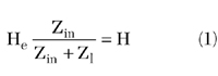
In the given approach, the oscillator is considered as a circuit consisting of two, two-port elements: an amplifier with a transfer function G(jw) and a frequency dependent feedback loop with transfer function H(j ) (see Figure 1 ). If the product of H(j )G(j ) is mapped in a complex plane, a closed curve is obtained. If this curve encloses a point (1+j0), the circuit under investigation is unstable and there is a possibility of the onset of oscillations. Using the given criterium, the G and H values should be measured in an open loop. At this stage of the development, designers meet a difficulty, which is connected with the necessity of open and closed loop equivalence. The input impedance of each two-port element is the load impedance for the other one. When the loop is unlocked a load impedance Zl must be connected to the output of the feedback circuit. This impedance must be equal to the input impedance of an amplifier. However, it should be noted that the value of each two-port element's input impedance depends on its load impedance, which is an input impedance for the next two-port element. Therefore, the load impedance for the open loop can be obtained only by iteration methods, which are time-consuming.
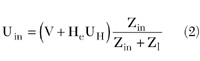
To overcome these difficulties, the following method of Nyquist criterium verification is offered. An independent AC voltage source is inserted between the amplifier and the feedback loop of a closed oscillator circuit. The input voltage of the amplifier element is Uin. The input voltage of the feedback loop can be written as UH = GUin. It is possible to represent the feedback loop (two-pole element H) as the series connection of an EMF source (HeUH) and a loading resistance Zl, loaded on the amplifier G with its input resistance Zin. The transfer function of the feedback loop can be written as
The independent AC voltage source V is inserted between the amplifier and the feedback loop. The input voltage is expressed as
Let

After simple mathematical manipulations, the dependence of Z on the product GH is given by
Z = (Zl + Z< sub >in)(1 - GH) (3)
With the help of Equation 3 a value of G(j ) H(j ) can be obtained (and, therefore, the stability of the oscillator circuit) by measuring Z.
The effect of the coefficient (Z< sub>l + Z< sub >in) is reduced by selecting the point where the voltage source is inserted, so that the value of this coefficient has a small dependence on frequency.
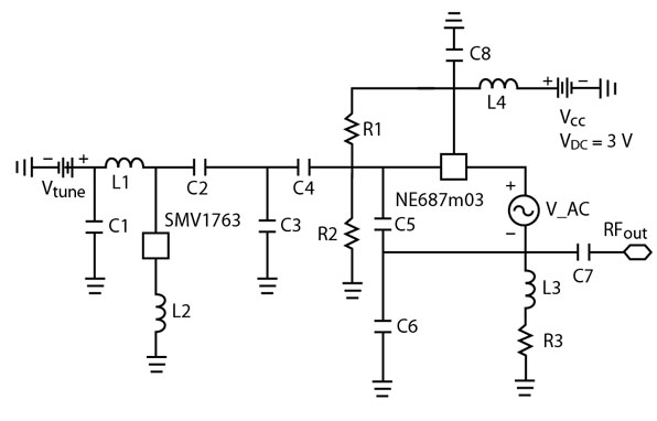
The software program, HP ADS 1.5, has been used for computer modeling of the given method. The circuit under test is a Clapp oscillator, designed for application in the frequency range of 2 to 2.3 GHz (see Figure 2 ).8 A low noise bipolar transistor NE687m03 (NEC Semiconductors) has been used as the active element of the amplifier. A hyperabrupt junction tuning varactor SMV1763 (Alpha Industries) has been placed in the resonant tank circuit for frequency tuning.
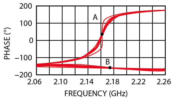
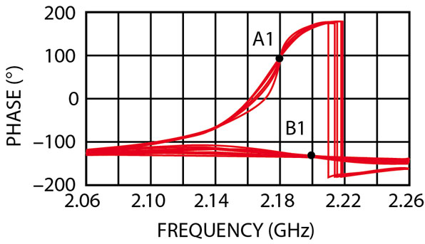
The test AC voltage source VAC with an amplitude of 1 V has been inserted into the emitter circuit of the oscillator. The AC analysis of the oscillator circuit has been conducted and the phase-frequency characteristic of the source current has been obtained (that is the dependence of the phase of 1/Z as a function of frequency). If the value of one of the circuit parameters, which does not have any sufficient effect on the oscillation frequency (the quality factor of the resonant circuit for example), is altered, a set of phase-frequency curves is obtained, as shown in Figure 3 . The curves are divided into two groups. The curves with the point of intersection B correspond to a stable circuit with no oscillation. The phase-frequency characteristics with the point of intersection A correspond to an unstable circuit where oscillation is possible. In other words, from the point of intersection of the phase-frequency characteristics the point (1+j0) in the plot of H(j )G(j ) can be determined. The point A phase must be equal to 0 in the ideal case, but in practice its phase is equal to the phase coefficient of (Zl + Zin).
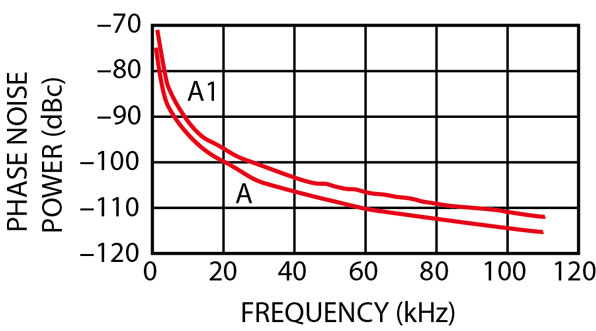
For VCO development, it is important to choose the circuit parameters so that the phase-frequency characteristic segments are symmetric on either side of the intersection point. In this case, the VCO oscillation frequency is close to the self-resonant frequency of the loaded tank circuit and the phase noise is minimized. In Figure 4 , the case of nonsymmetric intersection point (A1) is shown. This plot has been obtained by varying one of the circuit parameters. Figure 5 shows the VCO phase noise for the two circuit configurations (with intersection points A and A1). The phase noise of the oscillator with a symmetric intersection point in the phase-frequency characteristics (A) is improved by 5 dBc at 10 kHz offset.
Also, from the intersection point of the phase-to-frequency characteristics the frequency of oscillation can be predicted. For comparison, a harmonic balance (HB) analysis has been performed on the given VCO. Table 1 shows that the results of both analyses differ from each other by a very small amount (no more than one percent), and give a good prediction of the actual frequency range. The application of the given method of AC analysis allows the oscillator circuit stability and oscillation frequency to be determined with sufficient accuracy.
The VCO Development Procedure
The designing of frequency tuned oscillators is a complicated and time-consuming task. This article offers a procedure for oscillator development. At the initial stage of the circuit elements selection, the use of an AC analysis with the method described above is recommended. It allows the VCO circuit stability to be explored, and helps in the components selection and the choice of transistor operation mode for the given frequency range with minimum simulation time. Furthermore, the phase noise dependence on the circuit parameters can be predicted. Then, at the second design stage, it is convenient to perform the HB analysis. At this stage the oscillation harmonic frequencies and power can be determined, and the VCO phase noise explored. Many of the VCO characteristics are analyzed, such as output power variation, tuning nonlinearity, frequency drift with temperature, frequency pushing and pulling, and others. At the final stage of development, the transient analysis is carried out. It allows the amplitude and frequency of oscillation to finally be determined. Also, some time-dependent VCO characteristics, such as tuning speed, can be analyzed. The given VCO design algorithm allows the software programs available for circuit modeling to be used in a more rational manner and to minimize simulation efforts.
|
Table 1 | ||
|
|
Frequency (GHz) | |
|
|
V tune =0.5 V |
V tune =2.5 V |
|
AC Analysis |
2.051 |
2.352 |
|
HB Analysis |
2.035 |
2.344 |
|
Measured |
2.033 |
2.340 |
Conclusion
In the present article, the methods of computer analysis of oscillator circuits are discussed. Methods of oscillator stability determination and oscillation frequency prediction are offered. The modeling of the given method with the help of the software program HP ADS 1.5 has been performed on a voltage-controlled oscillator using a bipolar-junction transistor. The results of the simulations show small differences between the frequencies obtained with AC and HB analyses, and actual measured data. A generalized approach to the computer development of oscillators is offered.
References
1. K. Kurokawa, "Some Basic Characteristics of Broadband Negative Resistance Oscillator Circuits," Bell System Technical Journal , Vol. 48, 1969, p. 1397.
2. P. Shveshkeyev, "A Wideband VCO for Set-top Applications," Microwave Journal , Vol. 42, No. 4, April 1999, pp. 74-88.
3. R.G. Winch, "Wideband Varactor-tuned Oscillators," IEEE Journal of Solid-state Circuits , Vol. SC-17, December 1982, pp. 1214-1219.
4. D. Mitchell, "Microwave CAD Tools Simplify the Design of VCO," Microwaves and RF , Vol. 36, September 1997, p. 96.
5. Y.H. Kao and C.C. Chien, "Frequency Control in a Low Voltage, Wide Tuning VCO Design at 2.4 GHz," Microwave Journal , Vol. 44, No. 7, July 2001, pp. 128-140.
6. C. Schiebold, "Getting Back to the Basics of Oscillator Design," Microwave Journal , Vol. 41, No. 5, May 1998, p. 336.
7. A.V. Grebennikov and V.V. Nikiforov, "An Analytic Method of Microwave Transistor Oscillator Design," International Journal of Electronics , Vol. 83, December 1997, pp. 849-858.
8. Application Note 061, "W-CDMA 2.3 GHz VCO Using BFR360F and BBY58-02V," Infineon Technologies, 2001.
Yuriy Kitaev received his degree in radiophysics from Voronezh State University (VSU) in 1961 and his PhD in 1967. Currently, he is an assistant professor in the physics department at VSU. His current interests are in the field of microwave devices and drivers for acousto-optic devices.
Aleksey Shulga received his BS degree in electrical engineering and his MS degree in electrical engineering and computer science from Voronezh State University in 1999 and 2001, respectively. He is currently a research and development engineer at the Voronezh Institute of Communications (VNIIS). His research interests include microwave devices and circuits, wireless networks and mobile communications.