The rapidly increasing use of differential RF and microwave circuits has created many new measurement challenges. In S-parameter measurements, for example, transmission phase accuracy could often be ignored with little impact on specification-critical measurements. This is no longer true in the measurement of differential circuits, since seemingly small phase measurement errors can lead to substantial magnitude errors caused either by the processing of single-ended S-parameter data or impedance issues in test fixtures. The phase errors often arise from improper calibration or de-embedding procedures. To gain a better understanding of these errors, it is helpful to examine their sources and effects in the context of differential amplifier measurements.
In a traditional two-port, 50 Ω measurement environment, errors in phase, caused by calibration shortcuts or measurement mistakes, usually produce no ill effects other than in modeling activities. The device is typically connected with 50 Ω transmission lines and the ports are terminated, so there are no substantive standing wave issues. In addition, absolute phase shift is not often specified on many devices. While deviation from linear phase or group delay may be specified, a simple linear phase error does not trigger a problem with these characteristics. As a result, in terms of meeting specifications, these errors often go unnoticed.
However, in the increasingly common area of differential and non-50 Ω measurements, the data is being handled differently. Single-ended S-parameter data may be added or subtracted (in the linear sense) so phase errors are converted into magnitude errors, which affects insertion loss, gain and amplitude balance measurements. Many test fixtures are constructed with 50 Ω transmission lines, although the device and load impedances may be far from 50 Ω. The resulting mismatches make accurate phase compensation crucial for evaluating the true device performance. To fully understand the following discussion, it is necessary to have some knowledge of vector network analyzer calibration and mixed-mode S-parameters. Information on both topics is available elsewhere.1-3
Phase Error From Calibration
In addition to the usual issues of cable quality, cable flex, connector repeatability and instrument drift, calibration remains a main source of phase error. Calibration could be performed at the DUT or wafer level using special calibration standards, but since this is not often convenient, a connectorized approach is used. Connectorized devices or fixtures have ports of the same sex (such as SMA-F), so test cables are typically selected to match (that is all SMA-M). During the calibration, one or more thru connections are required, which raises the question of how to accurately calibrate when using two cables with male connectors.
The first option is to simply insert an adapter. While it is certainly the easiest approach, the analyzer will typically assume a direct connection (0-length thru), while the user is actually connecting a finite length thru. A typical GPC-3.5 FF adapter may be about 2 cm long, which corresponds to 24° at 1 GHz. This error will be incorporated into any transmission phase measurement.
The next option is to insert an adapter and allow the analyzer to correct for its length. This is a viable approach and will produce correct results. The only added uncertainty is knowing the adapter length, which can be measured using time domain or other techniques. The third option is to use a properly-characterized automatic calibration module. These modules are increasingly popular and can often be configured with a desired connector set to match that of the device under test (DUT). Assuming it is characterized in this state, the result will be correct.

The final approach is to use phase-equal insertables (PEI), which are precision adapters (MM, MF and FF) of precisely the same electrical length, so that one can be used during calibration and another during measurement. In this case, an FF PEI is attached to one cable during calibration so the thru can be connected, and replaced with an MF PEI for measuring the DUT. The only added uncertainty is in match and length differences between PEIs (< 0.1° at 1 GHz length difference). The sequence of events for a calibration and a measurement are shown in Figure 1.
Phase Error From De-embedding
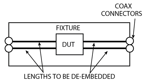
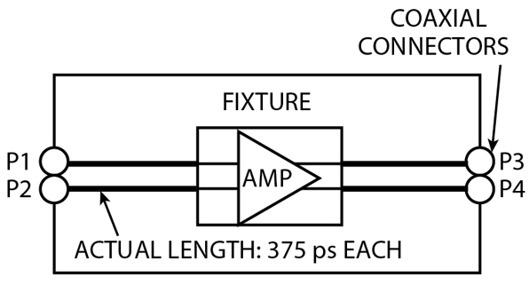
In a fixtured measurement environment, de-embedding is another source of phase error.4-6 At the lowest level, the de-embedding procedure usually consists of determining the phase length of the transmission lines linking the coaxial connectors (where the calibration is typically performed) to the DUT (see Figure 2).
There are two methods of finding these lengths. A short can be placed at the DUT plane, with the calibrated analyzer port connected to the coaxial connector. The theoretical value of S11 (ignoring loss) will be -exp(-jΒl) where l is the transmission line length.7 Thus, l can be calculated from the measured reflection coefficient. It is acceptable to use an air-equivalent dielectric for this measurement because an equivalent length is all that is needed for de-embedding. The second option is to use the time domain capability of a calibrated vector network analyzer to identify the location of the DUT plane relative to the connector.8 An air-equivalent length is acceptable (ignoring dispersion).
Errors can appear if a short is not used in the first method (relying on just the DUT's out-of-band reflection, for example), because some excess phase can be added into S11 to produce an inaccurate length measurement. Time domain measurement can produce inaccurate results if the base frequency range is too small, resulting in limited resolution.
New Effects: Phase Errors May Convert Into Magnitude Errors
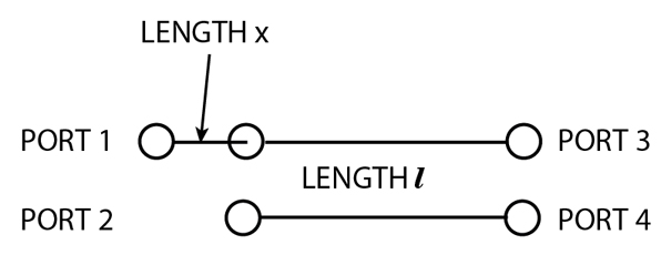
In balanced measurements the situation begins to change from the simple two-port measurement just discussed. Most vector network analyzer-based balanced measurements use single-ended S-parameters and then use linear combinations of these to simulate differential or common mode drive/reception.2 If phase errors are made symmetrically on these measurements, the consequences are similar to those for standard two-port measurements. An asymmetric error, however, can have more severe consequences. If the calibration is performed correctly in a balanced-pair transmission line example (see Figure 3), the measurement will be recorded as
S31 = e-j l
l
S42 = e-jl

where
Sd2d1 = differential transmission parameter
However, suppose that the port 1 reference plane is incorrect by a physical distance x (if, for example, an extra adapter was used during the thru step of the calibration and not compensated for). The results are then
S31 = e-jle-jx
S42 = ejl

In terms of the differential S-parameter, this phase error on one port has been converted into a magnitude error because balance has been disrupted. If x is electrically significant, this error can be substantial.
Multi-port Complications
Another potential problem arises in multi-port measurements. In multi-port calibrations, thru lines are connected between various port combinations, at least some of which overlap.2 If inconsistent reference planes are used in these different thru line measurements, more problems can arise. For example, an adapter may be required for the port 1 to port 2 thru connection but not the port 1 to port 3 thru connection in a three-port calibration. Since thru connections are used to determine load match, the values of port 1 load match as seen by port 2 and port 3 now differ. This error can propagate to other calibration coefficients, resulting in poor corrections and questionable measurement results.

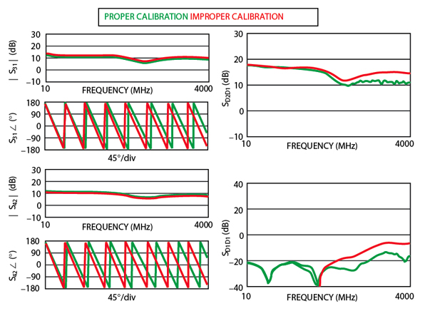
To illustrate the first of these problems, consider a balanced amplifier measurement. Each port is referenced to 50 Ω, all DUT connectors are SMA-F and all cable ends are male (see Figure 4). For the correct calibration, a PEI will be used on the port 1 cable. For the incorrect calibration, extra uncorrected adapters will be used for all three thru connections (1-2, 1-3 and 1-4). All thru lines are being handled in the same way so inconsistent reference planes will not be a problem. However, balance will be an issue with the incorrect calibration because the ports 1 to 3 phase length will be different from the ports 2 to 4 phase length (one extra adapter length built-in for the first path versus two built-in for the second path). The results are shown in Figure 5.
Compared to the proper calibration, the incorrect calibration produces only phase errors on the single-ended S-parameters as might be expected. The differential parameters suffer a worse fate, with up to a 4 dB error in gain and up to a 10 dB error in matching. The size of the errors increases with frequency because the electrical significance of the extra adapter length increases with frequency.
Differential Impedance Considerations
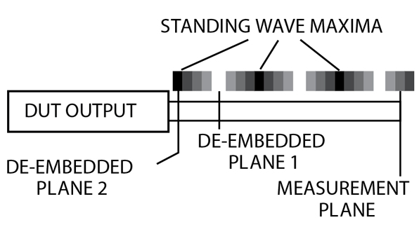
A third area of concern arises when the reference impedances are not 50 Ω.9,10 If the reference impedance is Z Ω, and if the fixture and associated transmission lines also have an impedance of Z Ω, then there would be no issues beyond those just discussed. Unfortunately, the DUT reference impedance may often be 150 to 200 Ω differential (75 to 100 Ω/port), but the fixture transmission lines are 50 Ω on each port (see Figure 6). Thus, there are substantial standing waves on all transmission lines. Phase errors (from inaccurate de-embedding, for example) can have a major effect because the reference plane is shifted to a different position on the standing wave.
To better visualize this problem, consider one of the simplest possible simulations: a dependent source with different input and output impedances and a voltage gain of 1. The output impedance and port 2 impedance are 100 Ω, while the input impedance and port 1 impedance are 50 Ω. Both sides will be connected with 50 Ω transmission lines (see Figure 7), hence the port 2 side will have standing wave issues. The magnitude of S21 for 50 and 60 mm transmission line lengths on the output is also shown. The effect of repositioning on the standing wave should be obvious.
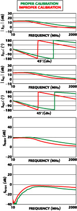
Significant magnitude problems can occur even if the phase errors are made symmetrically. As an example, consider another differential amplifier (see Figure 8) for which the calibration is performed correctly and the fixture de-embedding is performed incorrectly. The incorrect transmission line lengths will be entered on all ports so that the mistake will be symmetric. This time, however, the DUT impedance is 200 Ω differential and the fixture is constructed with 50 Ω transmission lines, so standing waves are substantial. The correct transmission line length is approximately 375 ps (air-equivalent) per port as determined by time domain methods. The erroneous value to be used is 300 ps/port (20 percent lower). The results are shown in Appendix A.
This time both single-ended and differential parameters are severely affected, which would be expected. Differential match errors as high as 7 dB are possible and the 3 dB bandwidth calculated from the data would change by about 200 MHz.

Conclusion
While phase errors in vector network analyzer measurements have always been possible, their impact has become more significant with the increased use of balanced devices and non-50 Ω reference impedances.
The cause of the significant phase errors that result often lies in calibration or de-embedding, but they can usually be quickly rectified with proper techniques. The impact of the uncorrected errors can be large in terms of both magnitude and phase, which affects insertion loss/gain and amplitude/phase balance measurements.
References
1. D.E. Bockelman and W.R. Eisenstadt, "Combined Differential and Common Mode Scattering Parameters: Theory and Simulation," IEEE Transactions on Microwave Theory and Techniques , Vol. MTT-43, July 1995, pp. 1530-1539.
2. Anritsu Co., "Three- and Four-port S-parameters: Calibrations and Mixed-mode Parameters," Anritsu Application Note 11410-00279, 2001.
3. G. Sundberg, "Grasping the Meaning of Mixed-mode S-parameters," Microwaves and RF , Vol. 40, May 2001, pp. 99-104.
4. R. Bauer and P. Penfield, "De-embedding and Unterminating," IEEE Transactions on Microwave Theory and Techniques , Vol. MTT-22, March 1974, pp. 282-288.
5. Anritsu Co., "Embedding/De-embedding," Anritsu Application Note 11410-00278, 2001.
6. L. Glasser, "An Analysis of Microwave De-embedding Errors," IEEE Transactions on Microwave Theory and Techniques , Vol. MTT-26, May 1978, pp. 379-380.
7. G. Gonzalez, Microwave Transistor Amplifiers , Prentice-Hall, 1984.
8. Anritsu Co., "Time Domain for Vector Network Analyzers," Anritsu Application Note 11410-00206, 1998.
9. R.B. Marks and D.F. Williams, "A General Waveguide Circuit Theory," Journal of Research of the National Institute of Standards and Technology , Vol. 97, September-October 1992, pp. 533-561.
10. Anritsu Co., "Arbitrary Impedance," Anritsu Application Note 11410-00284, 2001.
|
Appendix A Amplifier Performance with Correct (375 PS) and Incorrect (300 PS) Transmission Line De-embedding |
|
|