
A general trend in telecommunications, radar and other sensing applications is higher operating frequencies, into the mmWave bands. Though the bandwidth/throughput, spectrum congestion and resolution are attractive at mmWave frequencies, mainstream applications at these higher frequencies can interfere with critical military, government, weather sensing, satellite sensing, satellite communications and other scientific research. Ensuring minimum interference for critical applications in the mmWave spectrum will be a burden on the electromagnetic compliance (EMC) certification and electromagnetic interference (EMI) authorities, as well as anyone working in applications vulnerable to unintended -- or intentional -- interference.
A key antenna technology for testing and EMI/RFI monitoring/surveillance is the double-ridge guide horn (DRGH) antenna. This article explores the trends influencing the utility of DRGH antennas, their performance and technology developments.
DRGH ANTENNAS
Pyramidal horn antennas are widely used, classic aperture antenna configurations, where a rectangular waveguide is gradually transitioned into a horn, which provides an impedance-matched path from the waveguide to free space. These linearly polarized waveguide antennas have been a popular choice for many high gain, point-to-point radio links at mmWave frequencies. Closed-form equations enable a designer to closely match the antenna’s gain to its dimensions, and the radiation pattern can be closely approximated. However, these antennas typically perform over a relatively narrow bandwidth, which limits their use for certain testing scenarios. With EMI testing, for example, the immunity and emissions tests typically measure noise containing frequency components spanning a much wider bandwidth.
DRGH antennas introduce ridges - internal ridged arches attached to the edges of the pyramid on the E-plane - adding capacitance effects that lower the cut-off frequency of the dominant TE10 propagation mode, which extends the single-mode bandwidth. This eliminates the need for additional antennas to cover the required bandwidth, with their respective connections and potential paths for additional EMI.
The main DRGH antenna radiation pattern occurs on the main axis, i.e., at 0 degrees. At high frequencies, the main beam becomes narrower, and the side lobes increase in power. At high frequencies, i.e., >12 GHz, the main lobe splits into four off-axis lobes, where the amplitudes of these four lobes eventually surpass the power of the on-axis lobe.1
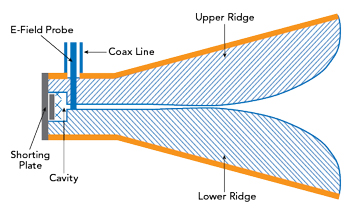
Figure 1 Side view of a DRGH antenna.
The components of a conventional DRGH involve the coax-to-waveguide feed, a standard pyramidal horn structure and two central ridges (i.e., top and bottom), as shown in Figure 1. Classic iterations of the DRGH antenna use dielectric sidewalls instead of the standard flared aperture found in horn antennas. The ridges are tapered to vary the impedance from the 50 Ω feed point to the impedance of free space at the aperture of the horn antenna, i.e., 377 Ω. The shielding ground of the coaxial feed is connected to the first ridge, the second ridge is connected to the center pin through an extension of the coaxial inner conductor. The cavity at the base of the structure is connected to the flared walls of the horn through a secondary metallic box, which creates a shorting plate that reduces the return loss in the waveguide transition.
DESIGN IMPROVEMENTS
Several design modifications have attempted to overcome the deteriorating radiation pattern at high frequencies.2–4 These include:
- Adjusting the ridges to reduce edge diffraction
- Modifying the side flares with a metallic grid, dielectric sidewalls or removing them entirely
Each of these approaches improves the bandwidth of the antenna by increasing the frequency where the characteristic deterioration of the radiation pattern occurs, extending it to Ka-Band.
In some DRGH antenna designs, the ridges have a “fast” opening or rapid transition from the waveguide to free space. The downside is particularly severe at the aperture: higher mismatch and unwanted loss. The sharp edges within the ridges can also cause diffraction affecting the radiation pattern at higher frequencies. To optimize this impedance transition, various ridge designs have been used: linear, exponential, circular or other mathematical functions - even sinusoidal. Some impedance tapers use a combination of linear (near the feed), exponential (in the middle) and circular (near the aperture) to improve the antenna’s performance.3
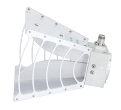
Figure 2 DRGH antenna with metal straps for the H-plane flares.
Modifying the side plates within the pyramidal horn structure includes completely removing the H-plane flares; adding dielectric H-plane flares; or adding thin metallic strips to form a bridge between the E-plane plates, which improves the structural integrity of the antenna (see Figure 2). The conventional DRGH has one ridge positively charged, the other negatively charged, which support an E-field between the ridges that propagates toward the aperture of the horn. With this design, a high E-field occurs between the ridges and a relatively low E-field between the ridges and the flares orthogonal to them, i.e., the flares that do not have ridges. This property makes these H-plane flares extraneous. They can be removed to reduce weight, with the additional benefit of increasing the half-power beamwidth at high frequencies.3