

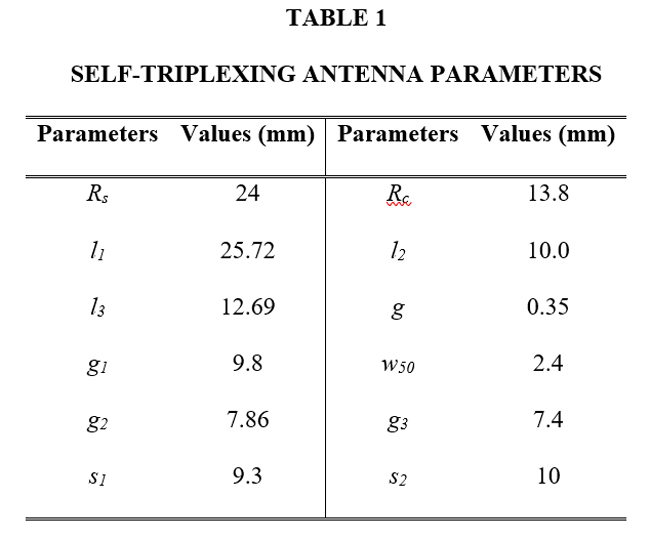
The design offers the flexibility to fine tune all three resonant frequencies independently without altering the original size. A parametric study of several critical parameters is shown in Figures 4 through 6. The resonant frequency ƒ1 is tuned from 5.6 to 5.73 GHz by varying l1 from 20.7 to 26.1 mm. By varying the position of the shorted vias along the radiating aperture, ƒ2 and ƒ3 are tuned (see Figure 4). As shown in Figure 5, ƒ2 is shifted from 6.5 to 6.9 GHz by varying s1 from 8.6 to 10.2 mm. Similarly, as shown in Figure 6, ƒ3 is shifted from 6.8 to 7.2 GHz by varying s2 from 9.3 to 11.1 mm. This shows each resonant frequency can be tuned independently; however, isolation is affected significantly and must be optimized, which can be accomplished with the aid of a commercial simulator. The optimized antenna dimensions are tabulated in Table 1.

Figure 4 S-parameters vs. changing l1.
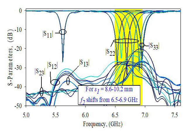
Figure 5 S-parameters vs. changing s1.
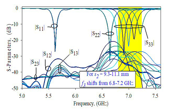
Figure 6 S-parameters vs. changing s2.
FABRICATION AND MEASUREMENT
A prototype of the design was constructed using the dimensions shown in Table 1. Conventional printed circuit board technology was used to fabricate the radiating element and plated-through via holes. A single-layered Rogers RT/Duroid substrate with a thickness of 0.78 mm and relative permittivity of 2.2 was used as the dielectric material. Figure 7 shows the prototype antenna.
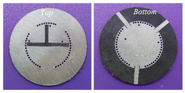
Figure 7 Fabricated antenna.
Figure 8 compares the measured S-parameters and antenna gains with the simulations. With port 1 on and the other ports terminated with matched loads, the measured resonant frequency was 5.64 GHz versus the simulated 5.6 GHz. The measured resonant frequency was 6.61 GHz versus the simulated 6.64 GHz with input port 2 on and the remaining ports terminated with matched loads. With input port 3 on and the remaining ports terminated, the measured resonant frequency was 6.97 GHz versus the simulation of 6.94 GHz. Measured port-to-port isolations were better than 23.8 dB at all operating frequencies.
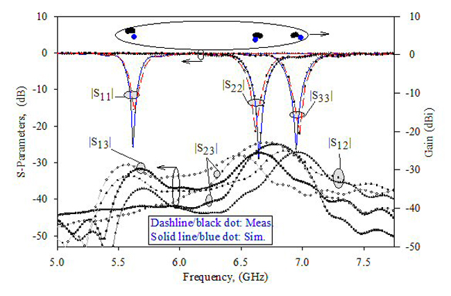
Figure 8 Simulated and measured results: S-parameters and gain.
The measured gains of the antenna at the three resonant frequencies was 4.48, 3.7 and 4.3 dBi, compared to the simulated values of 6.1, 4.9 and 5.0 dBi, respectively. The small differences between the measured and simulated results may be attributed to fabrication tolerances.
Far-field radiation patterns were measured in an anechoic chamber at a distance much greater than λ/2π. Figure 9 shows the radiation patterns in elevation (φ = 0 degrees) and azimuth (φ = 90 degrees) at the measured resonances. The patterns are oriented in the boresight direction.
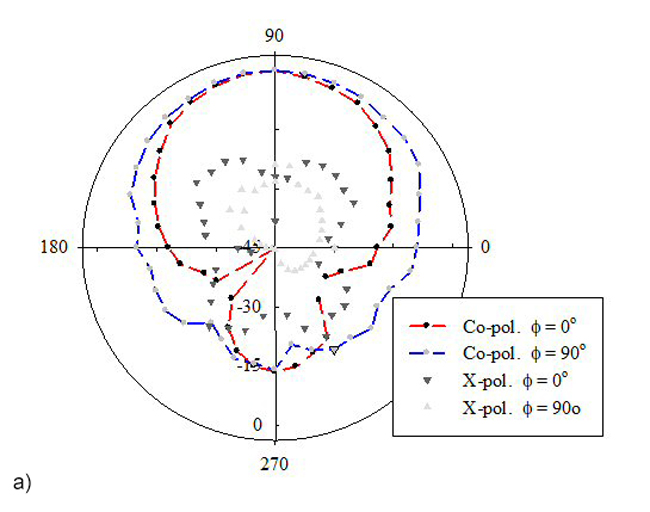
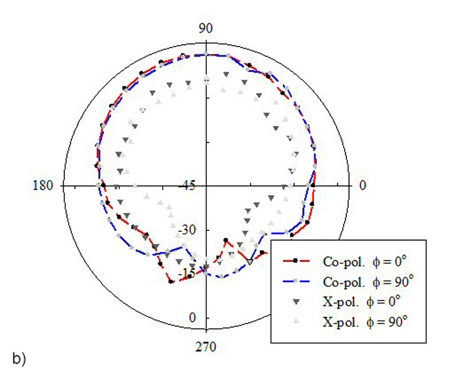
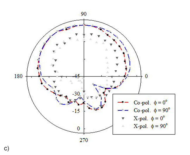
Figure 9 Far-field radiation patterns at 5.64 (a), 6.61 (b) and 6.97 (c) GHz.
CONCLUSION
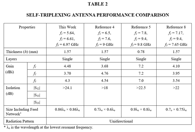
Table 2 compares the results from this design with previously reported work. This design uses a relatively compact structure to provide good radiation performance with excellent isolation. It uses the desirable features of metallic cavity-backed antennas and planar slot antennas, such as low-cost fabrication and ease of integration with other planar circuits.
References
- A. Kumar, D. Chaturvedi and S. Raghavan, “Design of a Self-Diplexing Antenna Using SIW Technique with High Isolation,” AEU-International Journal of Electronics and Communications, Vol 34, September 2018, pp. 386-391.
- H. Liu, W. Xu, Z. Zhang and X. Guan, “Compact Diplexer Using Slotline Stepped Impedance Resonator,” IEEE Microwave and Wireless Components Letters, Vol. 23, No. 2, February 2013, pp. 75-77.
- A. Kumar and S. Raghavan, “Planar Cavity-Backed Self-Diplexing Antenna Using Two-Layered Structure,” Progress in Electromagnetics Research, January 2018, pp. 91-96.
- P. Cheong, K. F. Chang, W. W. Choi and K. W. Tam, “A Highly Integrated Antenna-Triplexer with Simultaneous Three-Port Isolations Based on Multi-Mode Excitation,” IEEE Transactions on Antennas and Propagation, Vol. 63, No. 1, January 2015, pp. 363-368.
- A. Kumar and S. Raghavan, “A Self-Triplexing SIW Cavity-Backed Slot Antenna,” IEEE Antennas and Wireless Propagation Letters, Vol. 17, No. 5, May 2018, pp 772-775.
- A. Kumar, D. Chaturvedi, M. Saravanakumar and S. Raghavan, “SIW Cavity-Backed Self-Triplexing Antenna with T-Shaped Slot,” Asia-Pacific Microwave Conference, November 2018.
- A. Kumar A and S. Raghavan, “Design of SIW Cavity-Backed Self-Triplexing Antenna,” IET Electronics Letters, Vol. 54, No. 10, April 2018, pp. 611-612.
- D. Chaturvedi and S. Raghavan, “Low‐Profile Substrate Integrated Waveguide (SIW) Cavity‐Backed Self‐Triplexed Slot Antenna,” International Journal of RF and Microwave Computer‐Aided Engineering, Vol. 29, No. 7, December 2018.
- F. Xu and K. Wu, “Guided-Wave and Leakage Characteristics of Substrate Integrated Waveguide,” IEEE Transactions on Microwave Theory and Techniques, Vol. 53, No. 1, January 2005, pp. 66-73.
- A. Kumar, “Wideband Circular Cavity-Backed Slot Antenna with Conical Radiation Patterns,” Microwave and Optical Technology Letters, Vol. 62, No. 11, February 2020.