
Product Feature
WCDMA Application of Gain Blocks
EiC Corp.
Fremont, CA
This article deals with the detailed operating characteristics of InGaP HBT gain block products that are widely used in 2G, 2.5G and 3G applications, using 3G WCDMA as the example. The linearity, expressed by adjacent channel leakage ratio (ACLR), is studied and the gain and phase flatness of these products are measured.
|
Table 1 | |||
|
Part |
Gain |
P1dB |
OIP3 |
|
ECG001 |
19.0 |
12.5 |
26.0 |
|
ECG002 |
19.0 |
15.0 |
29.0 |
|
ECG004 |
15.5 |
13.0 |
27.0 |
|
ECG006 |
14.0 |
15.0 |
30.0 |
|
ECG005 |
18.5 |
18.5 |
33.0 |
|
EC1019 |
16.5 |
19.5 |
31.0 |
|
EC1119 |
13.5 |
19.9 |
33.2 |
|
EC1078 |
17.0 |
20.0 |
33.0 |
|
ECG003 |
19.0 |
23.0 |
36.0 |
|
ECG008 |
15.0 |
23.0 |
37.0 |
Product Families
The gain block products can be categorized into two families - the Darlington Amplifiers and the High Linearity Amplifiers. Both product families are made of extremely reliable InGaP HBTs fabricated using the company's proprietary process.1 The reliability in terms of transistor lifetime and product burn-in was previously reported.2 The transistor lifetime is shown in Figure 1 .
Fig. 1 In GaP HBT lifetime test results.
The Darlington Amplifier product series is listed in Table 1 . The Darlington Amplifier is a resistive feedback amplifier matched to 50 W with broad frequency band operation.2 A complete family of Darlington Amplifiers up to 24 dBm P1dB and 40 dBm OIP3 is offered.
The High Linearity Amplifier requires reactive matching. There are four parts in this series, as shown in Table 2 . A reactive matching circuit is required for each frequency band. They all offer approximately 24 dBm P1dB and > 40 dBm OIP3.
|
Table 2 | ||||
|
Part |
Gain |
P1dB |
OIP3 |
Frequency |
|
EC1089 |
12.2 |
23.5 |
42.0 |
1.9 |
|
ECG009 |
13.5 |
24.0 |
40.0 |
2.1 |
|
ECG014 |
18.0 |
24.0 |
41.0 |
1.9 |
|
ECG015 |
15.0 |
24.0 |
41.0 |
2.1 |
Experimental Results
For the 3G WCDMA application, ECG005 and ECG003 devices are selected from the Darlington Amplifier series, and ECG009 and ECG015 devices from the High Linearity Amplifier series. In the 3G applications, as well as many 2G and 2.5G improvement, there is an increasing demand on RFIC performance with respect to linearity, gain variation, phase deviation and output power. These RFICs are characterized over WCDMA applications.
The WCDMA basestation transmit frequency band centers on 2140 MHz with a 60 MHz bandwidth. The characterization is done over a much broader bandwidth for error correction application in the basestation transmit chain. Therefore, 2040 to 2240 MHz is used in this case.
Since the WCDMA channel bandwidth is 5 MHz, much broader than the 30 kHz of IS136 TDMA, 200 kHz of GSM/GPRS and 1.25 MHz of IS95, the gain variation becomes much more important.
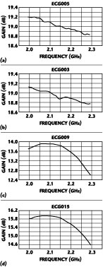
Fig. 2 Gain vs. frequency; (a) ECG005, (b) ECG003, (c) ECG009 and (d) ECG015.
Gain and Phase Flatness
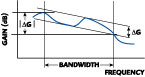
Figure 2 shows the gain versus frequency for the four RFICs. Since the Darlington Amplifier is a broadband design, its gain variation over 200 MHz is less than the reactively matched High Linearity Amplifier. In the case where gain equalization can be used, the equalized gain variation should be used instead of the absolute gain variation. The definition of these two cases is shown in Figure 3 .
|
|
|
|
Fig. 3 Definition of absolute gain variation | DG| and equalized gain variation DG. |
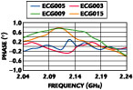
Fig. 4 Definition of phase deviation Df. |
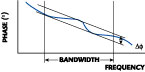
The phase deviation in the WCDMA application is as critical as the gain variation. Its definition is shown in Figure 4 , and the measured phase deviation of the four RFICs is summarized in Figure 5 . Less than one degree is measured across the 200 MHz band.
Table 3 summarizes the gain variation and phase deviation over different frequency bandwidths. The Darlington Amplifier, with its broad frequency band design, provides less gain variation over the 200 MHz bandwidth.
|
Table 3 | |||||
|
Part |
DG |
| DG| |
Df |
| DG| |
Df |
|
ECG009 |
0.35 |
0.70 |
0.7 |
0.17 |
0.25 |
|
ECG015 |
0.30 |
0.60 |
1.0 |
0.23 |
0.10 |
|
EC1019 |
0.10 |
0.60 |
0.4 |
0.10 |
0.20 |
|
ECG005 |
0.10 |
0.20 |
0.3 |
0.10 |
0.20 |
|
ECG003 |
0.10 |
0.23 |
0.5 |
0.09 |
0.24 |
Linearity Measurement in ACLR
The channel bandwidth of WCDMA is 5 MHz, which means ACLR is a critical measurement. The testing method, according to TS25.141, should use the test model 1, which has the following: PCCPCH + SCH + Primary CPICH + PICH + 64 DPCH. The Agilent E4432 signal generator is used for this test, the results of which are listed in Table 4 .
|
|
|
|
Fig. 5 Phase deviation vs. frequency. |
Fig. 6 Probability density vs. signal strength above the average power. |
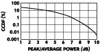
The test specification requires the ACLR to be better than 45 dBc. Figure 6 is the plot of the probability density versus signal strength above the average power. The signal of test model 1 shows a peak-to-average ratio of 8.5 dB at a probability density of 0.1 percent. The average power level with ACLR = 45 dBc is far below the P1dB. When the gain blocks are used as driver amplifiers, the modulated output signal must be very close to linear, and another 3 dB or so of power backoff will result in an ACPR of better than 50 dBc.
Each RFIC is tested for its P1dB and OIP3 across the 200 MHz bandwidth. In addition, ACLR was measured with the center frequency shifted accordingly. The output power level with ACLR = 45dBc is also recorded. The data clearly show that the output power level at ACLR = 45 dBc is approximately 7 to 8 dB below the P1dB .
|
Table 4 | |||||
|
Part |
Frequency |
P1dB |
Gss |
OIP3 |
Pout @ACLR= |
|
ECG005 |
2140 |
18.40 |
18.50 |
33.50 |
11.50 |
|
ECG003 |
2040 |
21.40 |
18.98 |
36.20 |
14.50 |
|
2110 |
21.20 |
18.90 |
35.50 |
14.00 | |
|
2140 |
21.10 |
18.86 |
35.00 |
14.00 | |
|
2170 |
21.00 |
18.80 |
34.00 |
14.00 | |
|
2240 |
20.80 |
18.78 |
34.00 |
14.00 | |
|
ECG009 |
2040 |
23.80 |
13.60 |
40.00 |
16.00 |
|
2110 |
23.80 |
13.70 |
40.20 |
16.00 | |
|
2140 |
23.80 |
13.60 |
39.80 |
15.50 | |
|
2170 |
23.60 |
13.48 |
40.00 |
16.00 | |
|
ECG015 |
2240 |
23.35 |
12.20 |
39.00 |
15.00 |
|
2040 |
23.20 |
15.80 |
40.00 |
16.00 | |
|
2110 |
23.46 |
15.80 |
40.20 |
15.50 | |
|
2140 |
23.50 |
15.80 |
40.00 |
15.50 | |
|
2170 |
23.50 |
15.80 |
40.00 |
15.50 | |
|
2240 |
23.60 |
15.00 |
40.50 |
15.00 | |
Conclusion
Two parts selected from the Darlington Amplifier series and another two from the High Linearity Amplifier series have been characterized for WCDMA application. Gain variation and phase deviation across the WCDMA bandwidth were measured and extended to cover the adjacent channels as well. Excellent results are achieved for products from both series.
ACLR versus output power level was also measured. In addition, the P1dB and OIP3 were recorded across the 200 MHz bandwidth centered at 2140 MHz. A detailed comparison shows that an ACLR = 45 dBc is achieved with an output power level of approximately 7 to 8 dB backoff from P1dB . This is consistent with the WCDMA signal's peak-to-average ratio. To maintain the linearity of the modulated signal, a minimum 10 dB backoff from the P1dB is recommended.
This characterization clearly shows that the gain block products satisfy not only the stringent demand of the 3G WCDMA, but can also serve many applications in the 2G and 2.5G, such as multi-carrier power amplifiers and other RF circuits in the infrastructure. More importantly, these products are made with the extremely reliable InGaP HBT proprietary process. Additional product information may be obtained from the company's Web site at www.eiccorp.com or via e-mail at sales@eiccorp.com.
References
1. B. Lin, "InGaP HBTs Offer Enhanced Reliability," Applied Microwave and Wireless , December 2000, pp. 115-116.
2. "High Reliability, High Linearity InGaP/ GaAs HBT Darlington Amplifiers: A Review of Its Reliability and a Discussion of Its Application," Application Note, EiC Corp., or visit www.eiccorp.com.
EiC Corp., Fremont, CA (510) 979-8953.
Circle No. 303