
A big benefit of the lower frequency bands is the signal propagation characteristics. The path loss for a transmitted signal increases with frequency by a factor 20log10(f). At the same distance, a signal at 28 GHz incurs 32 dB more loss than a signal at 700 MHz. With fixed maximum transmit powers for the base station; this increased path loss at high frequency dramatically reduces the coverage area for the 28 GHz equipment. The sub-6 GHz signals also have lower building penetration losses than mmWave signals. This becomes an important consideration for a 5G network deploying in large urban areas.
Sub-6 GHz networks also provide a clear advantage in multiple input, multiple output (MIMO) techniques and massive MIMO antennas. MIMO relies on multiple transmitters and receivers at the base station and user terminal. Because the radiators are physically separate, transmitted signals follow different paths to the receivers. Using spatial diversity and multiplexing techniques, coupled with multiple data streams on a channel and multipath propagation allows for more robust (better signal to noise performance) signals and/or higher signal data rates.
This MIMO antenna architecture will be a mainstay of most 5G networks, because to a first approximation, a MIMO antenna increases the channel capacity shown in Equation 1 by a factor of n, where n equals the number of antenna radiator pairs. In earlier 3GPP releases, antenna structures were limited to an 8T/8R configuration, meaning eight transmitters and eight receivers. The term “massive MIMO” (mMIMO) is also imprecise, but it has come to mean a number of transceivers much greater than eight. In current 5G deployments, we are seeing mMIMO base stations and access points with up to 1,024 radiators per antenna.
The reality of mMIMO is different for sub-6 GHz and mmWave implementations and this leads to subtle differences in the architectures and design criteria. Because of longer wavelengths, the sub-6 GHz signals undergo more transmission reflection than mmWave signals. This means a richer multipath propagation environment to enable the advantages of MIMO. In addition, establishing and maintaining an optimized wireless link relies on knowing the channel state information. This involves processing and updating information on parameters like scattering, fading, path loss, blocking, etc. These quantities are more repeatable at the sub-6 GHz frequency range, providing a more favorable environment for signal propagation.
ARCHITECTURE
These mMIMO antennas allow beamforming and beam steering and this is another key enabler. LTE antennas are typically static, providing energy throughout a sector, but 5G antennas form beams that can be steered in azimuth and elevation. Driving multiple radiators with signals of the appropriate amplitude and phase will form a beam. Changing the phase and amplitude to that group of radiators enables the beam to be steered off antenna boresight.
There are three distinct methods of beamforming/beam steering, each having advantages and disadvantages. Figure 3 is a representative block diagram for the RF front-end in an analog beamforming architecture. The advantage of this approach is simplicity, especially in the digital section. The antenna beam can be steered by adjusting the phase shifters and attenuators. The disadvantage is that only one data stream feeds the antenna elements, limiting the data rate and flexibility of this architecture.

Figure 3 Analog beamforming transceiver block diagram (source: Analog Devices, “Bits to Beams: RF Technology Evolution for 5G Millimeter Wave Radios”).
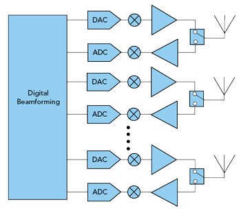
Figure 4 Digital beamforming transceiver block diagram (source: Analog Devices, “Bits to Beams: RF Technology Evolution for 5G Millimeter Wave Radios”).
Figure 4 shows the other end of the capability spectrum. This simplified block diagram represents a digital beamforming architecture. In this approach, each antenna has a dedicated RF chain and depending on the system requirements, silicon processes can fabricate this entire RF chain. In this architecture, all the precoding, multiplexing, signal weighting, phase shifting, etc. happens in the digital domain. The number of beams from the antenna is variable, as is the number of elements making up a beam. These beams are all steerable and algorithms can synthesize a drive signal to get most any beam characteristic. This architecture is easily the most flexible with the highest capability. This architecture increases the digital chip content, and this may increase cost and power consumption. Despite these challenges, digital beamforming architectures are currently in use in sub-6 GHz bands. Because of the substantial increase in performance and capability, expect to see more digital beamforming in the future in both sub-6 GHz and mmWave frequency ranges.
In response to these challenges, wireless equipment manufacturers have developed the hybrid beamforming architecture shown in Figure 5 as a compromise. This architecture incorporates the analog RF beamformer and front-end approach of the analog technique, along with the digital processing and independent data channels of the digital approach. The hybrid array will generate multiple beams, determined by the number of channels, but an RF chain drives a number of subarray “tiles,” rather than a single radiator. This compromise solution provides functionality closer to the digital architecture and complexity and power consumption closer to the analog architecture.
The hybrid and digital beamforming transceiver block diagrams illustrate why 5G deployments will become the new growth driver for the semiconductor market. More bands and mMIMO in the base station and more importantly, the handset implies a large increase in functional quantity. Each beam of the antenna requires a separate RF channel. The number of beams from an antenna depends on a variety of factors like the frequency range, the spatial multiplexing scheme, the number of users, etc., but we are seeing eight beams as a typical value in the early 5G deployments. This multiplicative effect of more beams and more RF content per sector times millions of 5G sectors has the semiconductor industry excited about the future.
BASE STATION SECTOR FORECASTS
Figure 5 illuminates another important topic for the semiconductor industry. As the diagram shows, there are several technology alternatives for this implementation. With cellular terminal sales flattening, 5G networks and devices are poised to become the most significant driver for the compound semiconductor market. The mix of sub-6 GHz and mmWave networks and devices, along with the relative shares of digital and beamforming architectures, will determine the growth trajectory for the various device technologies.
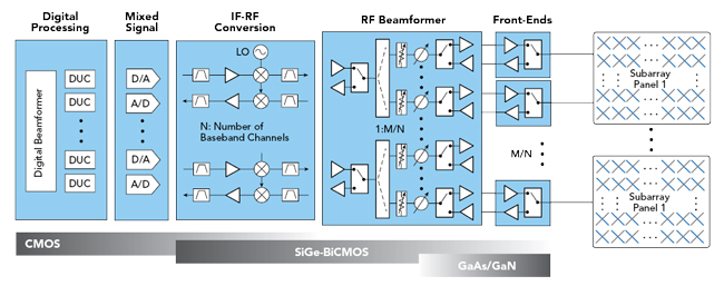
Figure 5 Hybrid beamforming transceiver block diagram (Source: Qorvo).
Figure 6 shows our forecast for new wireless base station sectors. Trends like remote radio heads, re-farming frequency ranges, adding capacity at existing sites, tower sharing, etc. make defining a “base station” increasingly difficult. To try to normalize these factors, we segment the base station market by sectors, where a sector contains all the electronics required to provide service to a pre-determined coverage area. With this definition, a conventional omni-directional macro cell will have three (or more) sectors, while a low power indoor cell may have only one sector. The other very important disclaimer is that we assembled these forecasts based on 2019 year-end data, without factoring in the effects of COVID-19 on global demand and the supply chain. Since this is an unfolding story, we are monitoring the effects of COVID-19 and we will update forecasts as trends become clearer.
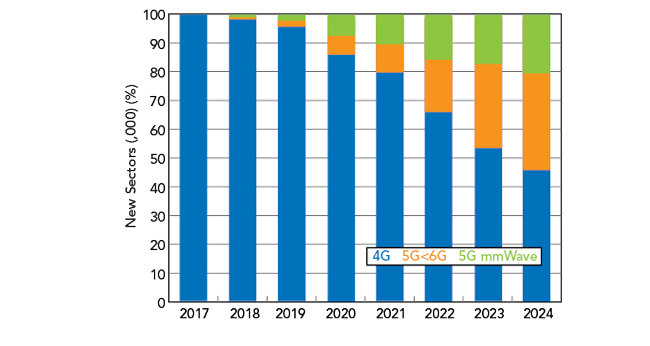
Figure 6 Wireless base station sector forecast (Source: Strategy Analytics).
The forecast shows some interesting trends, including the importance of the sub-6 GHz 5G segment to the wireless infrastructure market. The emergence of 5G does not foretell the end of 4G. The NSA versions of 5G will use existing 4G core infrastructure. Since it will take some time for 5G to become ubiquitous, the 4G network will evolve to provide 5G users with a robust experience during times when 5G coverage is not available. The first 5G network deployments were in the mmWave bands in the U.S. These deployments were primarily fixed wireless access applications, using a proprietary Verizon specification. These networks provided high speed “last mile” access to expand FiOS network coverage. We are forecasting that mmWave 5G networks will soon support mobility.
mmWave base station sectors will increase, but more slowly than the sub-6 GHz base station sectors. mmWave signals present many challenges, but for this forecast, the most important one is the smaller coverage footprint. With the small coverage area, it is very unlikely that operators will be able to approach ubiquitous coverage within the forecast period. As shown in the diagram of Figure 2, the most likely 5G network will be a hybrid of mmWave cells for high data rate capability, coupled with sub-6 GHz cells to maximize coverage area.
Growth of sub-6 GHz base station sectors tells a different story. The sub-6 GHz 5G bands are close to existing cellular bands. Incorporating these bands into networks and devices has not been a daunting challenge and initial network deployments accommodate mobility. Operators are deploying macro cells to establish coverage and then adding lower power small cells to improve coverage and capacity. This deployment model will drive fast growth in the sub-6 GHz segment, although the number of new sectors deployed in 2024 will be less than the number of new 4G sectors deployed. Our pre-COVID-19 sector estimate has the total market reaching nearly 10 million new sectors per year in 2024.
TECHNOLOGY SHARE FORECASTS
The estimated growth trajectory of 5G base stations sectors, coupled with the architectures discussed earlier influence the technology share. As wireless networks have evolved to 4G, the transceiver functional technologies have changed. Silicon IC technology has moved out toward the antenna, capturing share from compound semiconductor technologies. The increasing functional share of silicon in the block diagram relegates compound semiconductors to the beamformer and front-end functions.
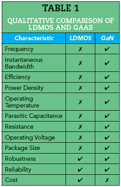
Within the front-end, the power technology transition is a major development that 5G will accelerate. Historically, Si-based laterally diffused metal oxide semiconductor (LDMOS) has been the dominant power technology. However, fueled by China’s massive LTE deployments, GaN has become the fastest growing base station power technology. This trend will speed up as 5G networks with mMIMO antennas, wider bandwidths, higher operating frequencies, reduced DC power dissipation, etc. deploy more widely. Table 1 shows a comparison of important performance characteristics.
The indications in Table 1 are anecdotal, qualitative and some comparisons may be a bit controversial, but the table gives a good visual indication of why GaN is quickly capturing share. Most of the green performance advantages result from GaN’s wide bandgap device characteristics. Reliability was an early disadvantage of GaN, but the supply chain has done a very good job at improving GaN design and manufacturing processes to eliminate these reliability concerns. The rapid adoption of GaN in defense and base station applications is another testimonial to reliability.
Perhaps the most controversial entry in the table is cost. This has been the topic of many discussions with the industry and the picture is still not clear. LDMOS proponents maintain that equivalent GaN devices remain substantially higher in price. Proponents of GaN may dispute that, but even if they agree, they point to total cost of ownership advantages with GaN technology. The broad acceptance of GaN in base station applications indicates that there is a compelling price argument for GaN.
Silicon-based LDMOS has been an extraordinarily resilient technology. That ecosystem has introduced several new generations, each with incrementally better performance and price to delay the loss of market share. While the latest generation of LDMOS performs to 4 GHz to capture opportunities in the 3.5 GHz band that is becoming a global de-facto standard, LDMOS devices will not operate in mmWave bands. The growth of the mmWave base station segment will hasten the overall market share decline of LDMOS.
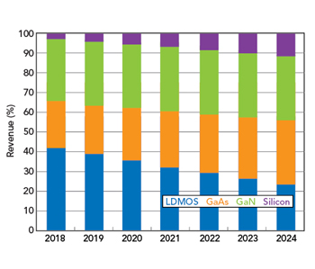
Figure 7 Sub-6 GHz base station power revenue by technology (Source: Strategy Analytics).
We estimate that GaN revenue in all base stations exceeded LDMOS revenue for the first time in 2019. However, LDMOS will continue to account for a significant share of the sub-6 GHz power revenue. Figure 7 shows an estimate of the power device revenue for the sub-6 GHz portion of the base station market. Despite the interest in the mmWave portion of 5G, revenue in the sub-6 GHz segment is non-trivial. We estimate that this revenue will reach nearly $300 million by 2024. Silicon (CMOS, SiGe) has the fastest revenue growth as sub-6 GHz base stations move to larger massive MIMO arrays that reduce the power amplifier transmit power. As operators seek to improve spectral efficiency to increase data rates with their limited channel bandwidths, the integration capabilities of silicon will be compelling.
Despite the integration benefits of silicon, GaN will account for the largest revenue in this segment. While the integration capability of silicon is compelling, the performance of GaN and the implications to operators for total cost of ownership are compelling. The advantages of GaN will allow this technology to capture a significant portion of the power revenue in the sub-6 GHz band. This revenue analysis includes driver amplifiers, largely the domain of GaAs devices in those applications where the entire RF chain is not integrated. The graph clearly shows that LDMOS revenue and share in this segment is shrinking. We do not expect it to disappear, but the technology is likely to find more use in niche applications in the future.
SUMMARY
Even before the COVID-19 outbreak, the compound semiconductor market was in the doldrums. Fortunately, 5G network and device deployments look to be the force that gets the market moving toward growth again. While mmWave frequencies offer some distinct advantages, the sub-6 GHz band offers the timeliest opportunities. The mix of frequency ranges and network architectures will determine the trajectory for compound semiconductor revenue growth, but we anticipate sub-6 GHz and mmWave 5G deployments will drive revenue in silicon IC, GaN, GaAs and LDMOS technologies.