
Product Feature
A Portable Base Station Installation and Commissioning Test System
Racal Instruments Limited
Slough, UK
Testing in the field puts singular rigorous demands on both the engineer and test equipment used, with the installation and commissioning of field installed base stations presenting particular challenges. Specific considerations include being able to keep downtime to a minimum, with demands for the tester to be easy to operate, provide high speed processing and offer reliability. Allied to these demands is the need for it to be portable, yet rugged enough to withstand the rigors of field operation.
With its modular design (Figure 1 shows the layout) and built-in self-test (BIST) facility, the 6413 BTS (Base Transceiver Station) test system fully meets these requirements. Designed to initially deliver 3GPP FDD capability it builds on the reputation of Racal Instrument's 6113 GSM base station tester. Its primary function is to provide adaptable on-site testing for the verification of both transmit and receive paths of base stations, making it an important tool in supporting both manufacturers and operators in the roll-out of new Universal Mobile Telecommunications System (UMTS) networks.
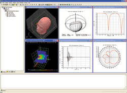
Fig. 1 The system's functional block diagram.
Incorporating features essential for on-site testing, the main-powered unit is self-contained, portable and rugged, consisting of a measuring transceiver, using high speed processing, connected via Ethernet to a laptop PC, thus providing swift transfer of commands and data. The base station connects to the 6413 via the normal RF antenna ports, using coaxial cable and to the backhaul connection via the network interface. Control of the testing environment is achieved by use of the loaded standards protocols through the network interface or via direct control through a local maintenance terminal (LMT).
The transceiver module operates over a frequency range of 400 MHz to 2.7 GHz, with an input power measurement accuracy of ±0.4 dB. The main interface is the measurement head, which, due to the modularity of its design, is capable of remote operation, a feature that will offer flexibility of design for future models. However, for this portable unit, it is incorporated within the instrument. The measurement head contains highly accurate power sensors, providing good control of the transmitted power level and accurate measurement of the receiver power level. Also, by having the capability of handling power levels up to 40 W, it can be connected directly to the basestation antenna port.
Fig. 2 Graphic representation of the base station output spectrum.
Test Features
Speed, simplicity and flexibility are the key features of the system's test operation. Specifically, the graphical user interface (GUI) runs on the PC and provides access to a full range of RF parameters as well as the network access settings for the modification of tests and the set-up of both the RF and backhaul links. All test results are stored on the PC, enabling easy export of data to other applications or hardware. Importantly, the 6413 makes full use of the PC and its display capabilities. For instance, the spectral estimation and constellation graphs (see Figure 2 ) give the engineer a graphical representation of the base station's outputs.
The test system allows all the standard measurement requirements to be performed, as per the loaded standard. An automated pass/fail test can be initiated that will test the full capability of the base station transceivers, with minimal manual interaction. Figure 3 shows the start-up test screen. The pass/fail limits can be set on a per test basis, or pre-set limits can be set and configurations can be called up within the user interface. The results can then be reviewed individually as the tests are executed, or captured and analyzed by the automated results analysis test system, giving the user a pass/fail indication at the end of the test run. Manual testing is also provided, with access to a suite of test parameters, allowing a wide range of measurements to be undertaken and to assist with fault diagnosis.
Fig. 3 The start-up screen.
A key feature of the test system is its capability for enhancement and customization, which enables testing to be tailored more precisely to either a network operator, or to those of the base station manufacturer. Customization can be extended to regional and geographical changes, allowing test suites to be tailored to installation environments as well as the base station types.
For example, a customer wanting to produce a test suite will, usually in consultation with its engineering team, decide what tests need to be carried out (and in what order) for a particular installation, produce a test suite and supply it to the field engineer. He then needs to make the two connections to the base station, one connection to the PC, run the test suite and get the result of the pass/fail test.
The standard transmitter tests which the 6413 supports are the measurement of the following: maximum output power up to +46 dBm with a test tolerance of ±0.4 dB; the spectrum emission mask in order to check that the broadcast has the correct roll-out rate; adjacent channel leakage ratio; common pilot indication channel (CPICH) power accuracy; occupied bandwidth; peak code domain error; error vector magnitude (EVM); and frequency error.
Fig. 4 Error vector magnitude graphical display.
In particular, the error vector magnitude test is important for wideband code division multiple access (W-CDMA) systems as it provides an indication of how much 'error' there is in a waveform, compared to the theoretical, thus indicating overall signal quality. Also vital is the frequency error measurement, which indicates whether or not the transmitter is within the frequency range it is intended to be transmitting in - the UMTS specifications require that a transmitter be within ±0.05 ppm of the assigned frequency. Figure 4 shows a typical error vector magnitude display and Figure 5 shows the error vector magnitude test parameter set-up screen.
Receiver tests that can be undertaken are measurement of the following: the reference sensitivity level, with the instrument capable of operating at low power levels; the internal bit error rate/block error rate (BER/ BLER); and the dynamic range - the instrument can encode the wanted signal down to a low level while in the presence of an internally generated additive white Gaussian noise (AWGN), which means the BER can be measured in the presence of additional interference signals.
Also, as the unit makes use of PC and Ethernet technology, the system can be enhanced to provide remote access. This allows for testing to be done without the need to have an engineer on site, allowing testing and monitoring to be run in quiet times, traditionally at night.
Fig. 5 Error vector test parameter screen.
Upgrading
Flexibility and adaptability are key features of the test unit. For instance, different manufacturers and standards can use different network connections for the backhaul links. This is not a problem for the 6413, however, as it can be fitted with up to two interface cards for base stations with differing backhaul interfaces. It can also be upgraded to a protocol analysis tool through an additional software package. This feature can be used in conjunction with dedicated scripts to simulate aspects of a real environment, such as call set-up.
There is also the potential for additional options to increase its capabilities because the hardware provided operates as a platform, allowing further protocol standards to be loaded as totally software options only. More importantly, all software can be upgraded in the field, facilitating the quick and easy addition of new features and enhancements, and support for ever-evolving standards. These upgrades may include updates to tests and performance.
The 6413 system is just one of the solutions from the 6400 series of products, which all share a common architecture. Thus, with additional options the instrument could go beyond measurements, yielding capabilities such as fault diagnostics and protocol analysis within a single box.
Conclusion
The 6413 test system has been developed as an easy to use tool for base station installation and commissioning in the field. The use of test sequences and the option to implement a single button pass/fail test allows a base station to be fully tested with minimal interaction from the engineer. With the capability for manual testing and the facility for users to tailor test suites for specific installations and environments the instrument can fit all expected test requirements. Future-proofing and upgrading features mean that technological developments and relevant standards can be implemented upon introduction. Also, due to its modularity and common platform, the test system will support further software options for other current and future generations of wireless base stations such as GSM (including GPRS and EDGE), UMTS TDD, TD-SCDMA and cdma2000.
Racal Instruments Limited, Slough, UK, + 44 (0) 1628 604455, sales@racalinstruments.com, www.racalinstruments.com.
Circle No. 300