
A 28 GHz beam steering cavity-backed slot antenna array for 5G cellular phones was implemented in the metallic casing of a mobile phone. The antenna array has eight cavity-backed slot array elements excited by two 4x4 Butler matrix feed networks (BMFN) that enable beam steering in desired directions with a coverage of approximately ±22 degrees. The measured 10 dB return loss band is from 26.2 to 29 GHz, and array element gain at 28 GHz is between 9 and 10.1 dBi.
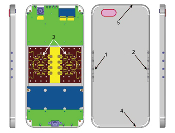
Figure 1 Front, rear and side views of the 5G cellular phone prototype.
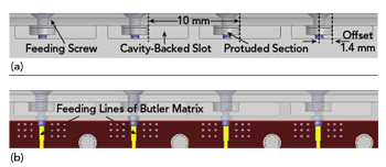
Figure 2 Beam steering array with four cavity-backed slots (a) and Butler matrix feed (b).
5G cellular networking will use mmWave technology due to the large available bandwidth at these frequencies.1-2 One differentiating feature of mmWave cellular communication is the use of antenna arrays at the transmitter and receiver for directional array gain. With antenna arrays, mmWave cellular systems can implement beamforming and beam steering at the transmitter and receiver to yield higher gain, compensating for frequency-dependent path loss, overcoming noise and reducing out-of-cell interference.2 The mmWave antenna for 5G smartphones is an important development for the mobile industry, and it can be regarded as one of the key enabling technologies to complete the transition from 4G to 5G networks.
Recent beam steering antenna designs for 5G cellular phones have yielded good performance using low-cost substrates,3-10 but these antennas may not be suitable for practical cellular phones, which employ metallic frames or casings. For example, Huo et al.10 use an antenna in package (AiP) module solution to realize beam scan; however, the configuration of their AiP modules is unsuitable for use in a metallic environment. Even if a glass or ceramic casing were employed, the metallic frame of the phone would still affect AiP module performance, especially its radiation pattern.
In this article, a novel 28 GHz beam steering antenna for a 5G metallic-cased phone is described. Two arrays, each with four elements, were integrated on each side of the metallic casing. To achieve the beam steering performance of the array, two 4x4 BMFNs were used. Due to the phase shifting limitation of the 4x4 BMFNs, beam steering performance is limited to four states. For a realistic cellular phone implementation, this antenna design concept can be used with a 5G transceiver for a continuous beam steering solution.
Figure 1 shows the prototype configuration. The cover of the phone is made of a metallic material. Identical beam steering arrays (1 and 2) are built on the left and right edges of the phone, respectively. Each beam steering array comprises four cavity-backed slot antenna elements excited by a 4x4 BMFN.3 The eight cavity-backed slot antenna elements are fabricated on the metallic back casing using a CNC lathe. The top and bottom metallic frames (4 and 5) are typically reserved for other antennas, such as 4G LTE main and diversity, GPS and Wi-Fi.
ANTENNA ELEMENT AND ARRAY DESIGN
Figure 2a shows the design of one of the beam steering arrays, where each of the four cavity-backed slot elements is fed by a small screw structure inserted across the cavity-backed slot, via a protruded section, and soldered to one of the feeding lines of the BMFN (see Figure 2b). The distance between the centers of the two slot elements is nearly 10 mm, which is approximately one wavelength at 28 GHz. To achieve a good impedance match, the center of the feeding screw is offset 1.4 mm from the middle of the cavity-backed slot. This array design, located at either the left or right edge of the metallic casing, ensures a good directional radiation pattern and high gain.
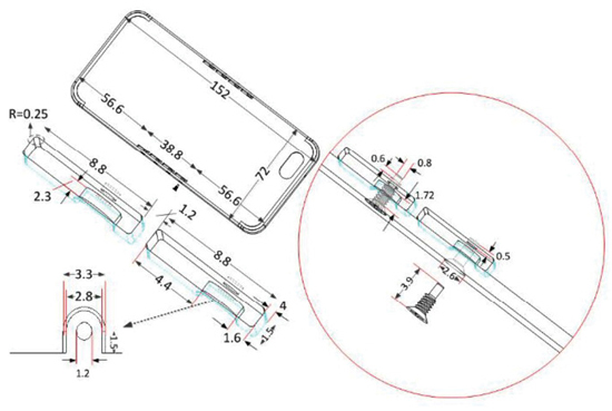
Figure 3 Antenna detail (dimensions in mm).