
This article describes the modeling of a SATCOM link, specifically the use case of using a satellite overlay to extend service continuity to IoT devices in a poorly covered rural area.
Non-terrestrial wireless networks (e.g., satellite constellations or high altitude platforms) have unique advantages—wide area service coverage and long-term reliability—which make them important components in the heterogeneous 5G global system of networks. Non-terrestrial networks (NTN) will likely play a critical role providing service to locations not covered by terrestrial 5G networks, such as rural and remote areas, moving platforms and disaster-stricken zones. One use case for NTNs is providing service continuity for machine-to-machine (M2M) or IoT devices as they move out of 5G terrestrial network coverage.1 This is particularly important for M2M/IoT devices which provide critical communications (e.g., applications in eHealth or vital asset tracking).
Narrowband IoT
Requirements for M2M and IoT communications can differ significantly from those for voice and data streaming: data throughputs are typically much lower. A prominent feature of M2M and IoT devices is a requirement for low-power consumption. Fortunately, these aspects of M2M/IoT communications can be simultaneously satisfied using a narrow bandwidth, low-power, wide area network (WAN). Narrowband IoT (NB-IoT) is an example of one such network standard, incorporated into 3GPP release 13 and further enhanced in releases 15 and 16 to ensure the ability to operate within a 5G ecosystem. The low signal power of these devices is accommodated through the lower bandwidth of the NB-IoT standard, which helps to reduce RF noise. Fortunately, this narrow bandwidth requirement is consistent with the low data rates acceptable for these communications.
NB-IoT is based on a simplified LTE standard with a maximum bandwidth of 200 kHz, transmitted either in dedicated bands, in-band within LTE or 5G NR carriers or within their guard bands. The peak downlink and uplink rates using the full bandwidth are 250 kbps; systems with lower data throughput can use individual subcarriers.
LEO Satellites
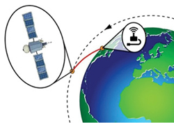
Figure 1 A LEO satellite can communicate with IoT devices in rural or remote regions.
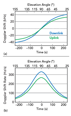
Figure 2 Doppler shift (a) and Doppler drift rate (b) for a satellite in LEO orbit.
While satellite networks have the advantages of wide service coverage and reliability, their communication links unavoidably suffer from comparatively large latencies and propagation losses. To minimize both, satellite constellations in low Earth orbit (LEO) can be used to communicate with NB-IoT devices on the ground (see Figure 1). For example, the round-trip latency for a LEO satellite orbiting at 1000 km is less than 10 ms when the satellite is directly overhead. The free space propagation path loss, FSPL, is given by the Friis transmission formula:

where d is the distance and λ the wavelength. The FSPL is the dominant contributor to loss in the satellite link budget and is minimized by the smaller propagation distances associated with a LEO satellite and using larger wavelengths. For λ = 14 cm (a 2.1 GHz carrier) and d = 1000 km, the FSPL = 159 dB for a satellite directly overhead (elevation = 90 degrees). The propagation path increases for lower elevation angles due to the longer slant range to the satellite associated with line-of-sight (LOS) propagation with refraction and absorption in the Earth’s atmosphere. Using L- and S-Band carriers, rather than higher frequencies, keeps the atmospheric absorption relatively small.
LEO satellites have the disadvantage of the communications channel being complicated by relatively large Doppler shifts. To maintain its orbit, a LEO satellite at an altitude of 1000 km must have a velocity, v, of 7.4 km/s. The Doppler shift due to this motion is given by:
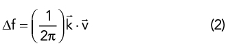
where k⃗ is the wave vector of the radio signal at the position of the satellite. The wave vector has a magnitude of k = 2π/λ.
For a LEO satellite in polar orbit, Figure 2a shows the Doppler shift as a function of time for downlink and uplink carrier frequencies near 2 GHz, where t = 0 is the instant when the satellite passes directly overhead. The corresponding elevation angles are shown on the upper axis. The uplink (UL) (1.7 GHz) and downlink (DL) (2.1 GHz) signals experience different shifts due to their different wavelengths. To accurately account for the direction of the signal wavevector k⃗ at the location of the satellite, an in-house ground-to-satellite propagation model based on ITU-R P.676-112 and ITU-R P.834-83 has been used to account for the refraction in the atmosphere (which bends the radio wave toward the surface of Earth) compared to direct LOS propagation. The time rate of change of the Doppler shift is shown in Figure 2b. To avoid inter-band interference, the common mode component of the shift must be dynamically compensated for by the satellite, with the remaining differential shift across a coverage area being compensated for by the user equipment (UE).4