

All 5G NR FR1 deployments are currently based on time-division duplex (TDD) and use unpaired frequency bands, typically in the 3.5 GHz frequency range. The second phase of 5G NR network deployments, anticipated for 2020, will use frequency-division duplex (FDD) mode, as almost 90 percent of the spectrum below 8 GHz is organized as paired frequency bands, where downlink and uplink use different frequencies. All the targeted frequency bands, however, are already in use by 4G LTE. By adding spectrum sharing capabilities to the 5G NR standard, this spectrum can be accessed while in use, enabling coexistence between 4G LTE and 5G NR. The sharing of the spectrum allows network operators a smooth transition from LTE to 5G without the need for spectrum refarming. This article discusses the required feature sets, summarized as dynamic spectrum sharing (DSS), and analyzes related test and measurement challenges for network and device testing.
The first 5G NR networks are on-air using network deployment option 3X and utilizing E-UTRA NR Dual Connectivity (EN-DC) with a split bearer setup. In this deployment scenario, the so-called non-standalone (NSA) mode, an LTE anchor is required to exchange control and signaling information. In addition to LTE signaling, the anchor is also required to configure, add, modify and release the connection to the 5G NR radio access network (RAN). In this setup, the LTE base station (eNB) takes on the role of the master cell group, where the 5G base station (gNB) becomes the secondary cell group. Both RANs connect to the existing LTE core network, the evolved packet core.
According to the 3GPP standard, carrier aggregation can be activated for each cell group. However, today's 5G deployments at sub-8 GHz frequencies, also called frequency range 1 (FR1, from 410 MHz to 7.125 GHz), combine multiple LTE carriers with typically one NR carrier. A vast majority of these networks worldwide use 3.5 GHz, with a carrier bandwidth of up to 100 MHz, applying 4 x 4 MIMO and using TDD mode.
Due to various local regulatory requirements, the 3.5 GHz band comprises three different frequency bands from a standardization perspective. These are n77 (Asia), n78 (Europe) and n48 (USA).1 As the majority of frequency bands worldwide are FDD and used by LTE, the first 5G NR network deployments took advantage of the underutilized TDD frequency bands, including 3.5 GHz. The first generation of 5G modems and, subsequently, the first generation of 5G mobile devices do only support the TDD mode for FR1. FR1 FDD is something that the industry is still working to commercialize.
THE NEED FOR DSS
Not all service providers own spectrum licenses within a TDD band. To take advantage of 5G with optimized quality of service, to lower latencies and to further address the new market verticals (e.g., automotive and industrial), a network operator must transition to standalone (SA) mode, in which the 5G RAN is connected to the 5G core network (5G-CN, option 2). There are several intermediate steps (options 4, 5 and 7) defined that lead toward a standalone deployment. Which path an operator follows is up to its 5G deployment strategy. For a detailed description of these options and other fundamental aspects of the fifth generation of wireless communication, please refer to Kottkamp et al.2
Due to the occupation of its FDD-based spectrum assets, service providers are forced to choose between the acquisition of new spectrum or refarm spectrum already in use. Both options are costly. Therefore, the 5G NR standard offers the possibility of adapting to existing LTE deployments and sharing the spectrum used exclusively by LTE today. The enabling feature is called DSS, which is part of the overall mechanism allowing NR and LTE to coexist while using the same spectrum.
Another feature that enables NR LTE coexistence is the decoupling of downlink and uplink transmissions, necessary due to coverage issues in the uplink direction at the FR1 midrange frequency bands of 3.5 GHz and above. This feature results in a function called supplemental uplink (SUL) that allows a device to switch its uplink transmission from the midrange spectrum to the low band spectrum based on received signal quality. This feature is not discussed in this article, as the industry is currently focusing on DSS.
In the long term, DSS enables network operators to provide a coverage layer for 5G using the lower frequency bands, typically targeting frequencies below 1 GHz. DSS needs infrastructure updates, advertised as software-only updates, but also requires the second-generation of 5G chipsets and handsets taking advantage of these new modems. The rollout of DSS is expected early to mid-2020.
THE AWAKENING OF MBSFN
DSS has an impact on both LTE and 5G NR standards. The effect on LTE is marginal, as it is hard to change a successfully deployed technology to enable its successor. A 5G NR device needs to detect the synchronization signal blocks (SSB) to access the network. To maintain synchronization in time and frequency, these SSBs need to be sent periodically by the network, with a gap defined to transmit the SSB on an already occupied frequency channel used by LTE. The ideal feature to allow this gap in a continuous LTE transmission is to use multimedia broadcast single frequency network (MBSFN) subframes. Defined initially to enable broadcast via an LTE network and, therefore, make the transfer of content more efficient than unicast transmissions, this feature is part of the evolved multimedia broadcast multicast services (eMBMS) functionality; eMBMS is part of 3GPP’s release 9 set of technical specifications.
Six out of ten subframes forming the LTE radio frame can be configured by the network to become MBSFN subframes. Based on the standard, this could be subframes 1, 2, 3 and 6, 7 and 8. To minimize the impact on the performance of LTE, typically only one subframe out of the six possible subframes is configured to be an MBSFN subframe. The applied configuration is broadcast by the LTE network with system information block type 2 (SIB2). This is the same SIB that informs a 5G-capable terminal that the LTE serving cell can connect the handset to the 5G RAN. A standard LTE terminal would read in the MBSFN configuration from SIB2 and ignore the subframes configured for broadcast. Initially, DSS is tested based on NSA mode; thus, the 5G handset would have two radios active, LTE and 5G NR.
The LTE portion will follow the same principles as an LTE-only device. However, the 5G NR part of the handset, scanning the targeted frequency band for sharing, will detect the transmitted SSB within the open LTE subframe on the desired frequency channel. As DSS is intended to provide a coverage layer for 5G, typically frequency bands below 1 GHz are shared between LTE and 5G NR. Initially, a subcarrier spacing of 15 kHz is used for 5G NR to avoid interference between both technologies, resulting in the same number of subframes used in LTE and 5G NR. Based on the mapping principles for SSB for 15 kHz, defined as case A, the targeted frequency band below 1 GHz leads to a maximum of four SSBs transmitted by the 5G network.
Typically, the SSBs are transmitted by the network in the first half-frame (5 ms) of a radio frame. As it is not possible in LTE to configure subframe 0 for MBSFN, subframe 1 is configured as the MBSFN subframe, so it can carry SSBs. However, an MBSFN subframe is never entirely empty. There is a non-MBSFN region defined that can be one or two OFDM symbols long, dependent on overall signal bandwidth. This region is intended to carry the control channels for LTE, such as the physical hybrid ARQ channel, the physical control format indicator channel and the physical downlink control channel (PDCCH). Therefore, any NR transmission can only start at OFDM symbols 2 or 3 within an MBSFN subframe.
The requirement to transmit control information for NR, to schedule the reception of NR’s physical data shared channel (PDSCH) and the necessity to map a demodulation reference signal for the data channel to the beginning of the subframes lead to the configuration illustrated in Figure 1. Out of the total 14 OFDM symbols forming a subframe of 1 ms duration for subcarrier spacing of 15 kHz in one 5G NR slot, only 12 OFDM symbols are available for NR transmission. For proper demodulation of the PDSCH and to enable mobility, a second symbol carrying the PDSCH demodulation reference signal (DMRS) for the data channel is required. This additional symbol is symbol 9, as shown in Figure 1.3
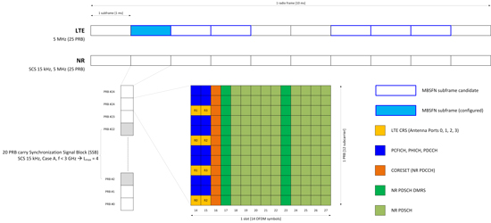
Figure 1 NR signal configuration within the MBSFN subframe.
INCREASING CAPACITY AND IMPROVING 5G NR WHILE DSS IS CONFIGURED
With just one subframe available for 5G NR, the technology operates under its potential. Therefore, DSS additionally enables the use of subframes that are dedicated to LTE and not configured for MBSFN via two distinct features:
- Depending on the MIMO mode (2 x 2, 4 x 4), standard LTE subframes include cell-specific reference signals (CRS) mapped to certain resource elements in the time-frequency grid. An LTE terminal uses CRS for channel estimation and to maintain full synchronization in time and frequency. Assuming a simple scenario where, based on the current load situation, the scheduler in the LTE base station is not mapping any data into such a subframe, the LTE CRS would still be present, maintained and transmitted.
To enable NR to use these subframes, rate-matching around LTE CRS is adopted by the standard. Several factors impact the rate-matching algorithm. The first parameter is required to align the subcarrier positioning for 5G NR related to LTE. The value corresponds to the offset to point A divided by 15 kHz. Second, the bandwidth and number of antenna ports used by LTE must be known, as the MIMO mode dictates the mapping of CRS per antenna port. As mentioned earlier, DSS targets frequencies below 1 GHz; therefore, typically two antenna ports (2 x 2 MIMO) are used. Lastly, the factor vshift represents the impact of the physical cell identity (PCI; vshift = PCI mod 6), which defines the starting point (subcarrier) for the mapping of the LTE sequence used for generating CRS. Figure 2 displays all required parameters to configure the LTE CRS rate-matching algorithm on the R&S®SMW200A vector signal generator, intended to perform physical layer testing of the 5G modem.
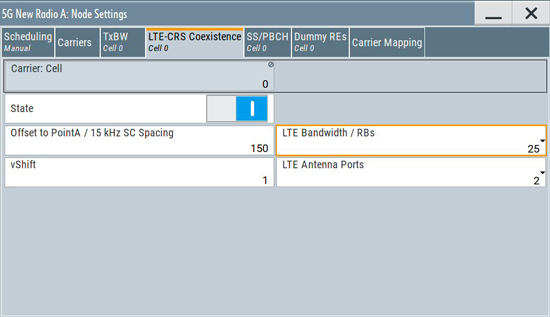
Figure 2 LTE CRS coexistence setting for the R&®SMW200A vector signal generator.
In a real network, this information is signaled to the device via the dedicated radio resource control (RRC) connection. As NSA mode is the initial deployment mode for DSS testing, this information is sent over the established LTE connection to the device. In SA mode, it would be sent over the NR RRC connection.
- The second feature is the support of an additional position for the mapping of the PDSCH DMRS. Based on a standard LTE subframe, with the LTE control channel and CRS present, and assuming the scheduler does not schedule any PDSCH, the remainder of the subframes are available to 5G NR. Therefore, the control resource set (CORESET) and the NR PDSCH with rate-matching active, including DMRS, are mapped on the available resource element (see the example in Figure 3). Due to the CORESET occupying OFDM symbol 2, the first PDSCH DMRS is assigned to symbol 3. The position information (l0) of the OFDM symbol (2 or 3) that carries the first DMRS is indicated with the master information block carried by the physical broadcast channel as part of the SSB. To support mobility, proper channel estimation is a prerequisite that can only be guaranteed if at least two symbols within a slot carry PDSCH DMRS. According to 3GPP TS 38.211 V15.6.0 (2019-06),3 for the provided example, this additional symbol to carry DMRS would be OFDM symbol 11. However, from an LTE perspective, CRS is still present and transmitted in this symbol; therefore, the additional position of the DMRS must move from symbol 11 to symbol 12 (see Figure 3). This feature is a device capability, which means the device signals its support of this functionality to the network during the initial registration process.
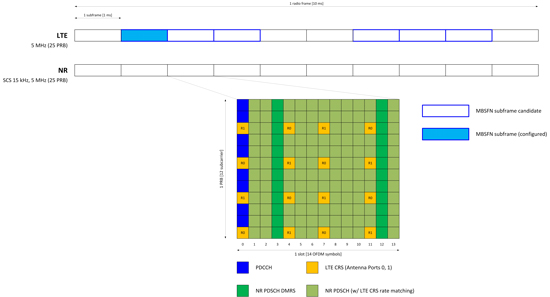
Figure 3 NR using standard LTE subframes with CRS rate-matching and additional DMRS position.
In general, this change is only applicable if three conditions are fulfilled: First, the device needs to have submitted the support of the capability to the network; second, the network has configured the device with the rate-matching parameter for LTE CRS via RRC; third, the first position of the PDSCH DMRS is set to l0 = 3.