

WHERE IS THE DYNAMIC SHARING ELEMENT?
Up to now, what has been discussed is a semi-static configuration of both LTE and NR to enable the use of specific subframes for NR when LTE is not present or mechanisms that allow NR to transmit in LTE subframes not used by LTE but where essential LTE signals components are still sent. The question is whether there is a way for LTE and NR to share a subframe and for both to transmit control information (PDCCH and CORESET) and data (PDSCH)? The answer is yes.
So far, the discussion has focused on the fundamental mapping of the data channel and corresponding DMRS for 5G NR based on the so-called PDSCH mapping type A. But the 3GPP standard also defines PDSCH mapping type B. The difference between these two is that type A defines the mapping relative to the slot start, where type B represents the mapping relative to the beginning of the PDSCH within the slot. PDSCH mapping type A allows, according to the standard, a maximum symbol offset of 2, which, under certain conditions, is not favorable when applying DSS between LTE and 5G NR. PDSCH mapping type B overcomes this drawback. Figure 4 shows a configuration example for LTE with a 5 MHz channel bandwidth, where NR is transmitted on the upper 6 out of 25 resource blocks.
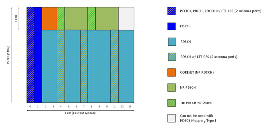
Figure 4 Dynamic sharing of a subframe between LTE and 5G NR.
COORDINATION, COORDINATION AND, AGAIN, COORDINATION
All described physical layer features require coordination among both RANs as in a dual connectivity approach; both (LTE and NR) use two independent schedulers. The resulting E-UTRA NR cell resource coordination procedure (see Figure 5) that can be triggered by both nodes over the Xn interface is defined in 3GPP TS 38.423 V15.4.0 (2019-07), NG-RAN.4
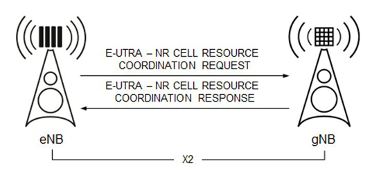
Figure 5 E-UTRA NR cell resource coordination procedure.
The process allows the coordination of scheduling resources in the frequency and time domains at the medium access control layer in both base stations. When initially testing DSS in NSA mode, the coordination process is triggered by the eNB. In its request message, the eNB sends the data traffic resource indication toward the gNB. This information element contains the information if the sharing is in uplink only or for uplink and downlink. For the latter case, two individual bitmaps are provided with the message, containing a bitmap between 6 and 17,600 bits long. Each position in this bit string stands for a physical resource block (PRB) pair that is reserved for E-UTRA if it is set to 1 and is not used for E-UTRA when it is set to 0. The bit string may span multiple contiguous subframes. The first position of the data traffic resources information element corresponds to the receiving node’s subframe 0. The length of the bitmap is an integer multiple of the bandwidth. Assuming the signal bandwidth to be 5 MHz (25 PRB), a total of 704 subframes are addressed through the bitmap. The bitmap length doesn’t provide the flexibility to address all subframes within radio frames, which makes it necessary to provide information for which the system frame number within the bitmap becomes active. Figure 6 is an example of the bitmap. Based on this configuration, resource blocks 15 to 24 in subframe 0 (light blue), resource blocks 5 to 24 in subframe 1 (green), resource blocks 3 to 17 (brown) and resource blocks 8 to 22 (purple) in subframe 703 can be used for 5G NR transmission and reception.
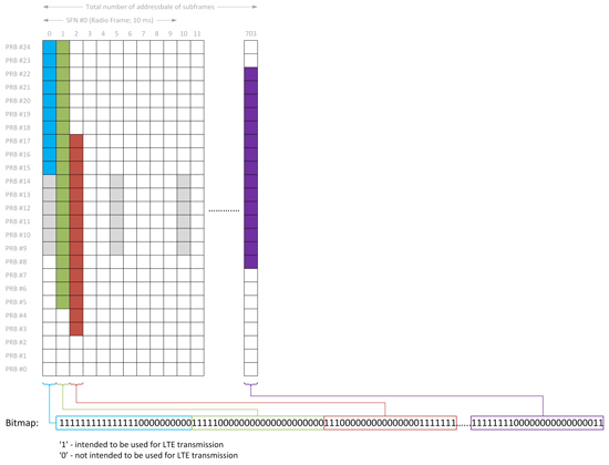
Figure 6 Data traffic resource pattern for NR LTE resource coordination (5 MHz, 25 PRB).
Other resources in LTE are protected through the exchange of the protected E-UTRA resource indication message between the eNB and the gNB during the setup of the X2 interface, which is a separate but mandatory prerequisite. As explained earlier, LTE configures MBSFN subframes to allow the transmission of SSBs for NR. These subframes are protected from the above configuration by additional information provided by the data traffic resource indication as a reserved subframe pattern.
TESTING FOR DSS
DSS is a powerful feature, but it requires extensive testing for several reasons. This applies to lab-based LTE and 5G user equipment testing as well as carrying out network performance measurements using scanners (sensitive receivers) and devices to estimate coverage and end-to-end (E2E) performance.
The activation of DSS within the network should not create any interference for the exiting LTE deployment. LTE-only devices must not suffer any interference or impact when configuring MBSFN subframes within the network. Further, with MBSFN active, end-to-end throughput tests are required to ensure minimal impact on LTE performance. While 5G NR, including SSB, are transmitted within MBSFN subframes, receiver sensitivity tests for LTE devices must be favorable, to ensure sensitivity requirements are still met by the device when 5G NR is present within the channel at defined subframes.
A 5G NR capable device must be able to synchronize in time and frequency with the 5G RAN when SSBs are transmitted within MBSFN configured subframes. When 5G NR is sent in non-MBSFN subframes using an LTE CRS rate-matching pattern for NR’s PDSCH, a data throughput test is adequate to verify correct implementation of the stack features. Advanced device testing includes dynamic scheduling procedures that mimic the described E-UTRA NR resource coordination procedure, where data is scheduled according to data traffic resource indication, including the validation of PDSCH mapping types A and B. The new R&S CMX500 mobile radio tester platform from Rohde & Schwarz, in combination with the R&S CMW500 wideband radio communication tester, is an example of an appropriate tool to carry out these extensive test scenarios on mobile devices supporting LTE and 5G NR (see Figure 7).
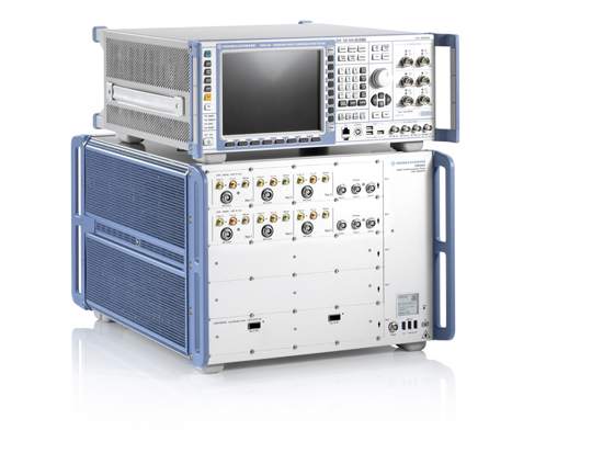
Figure 7 R&S CMW500 and R&S CMX500 for testing mobile devices supporting 5G NR, LTE and legacy technologies.
DSS has a further impact on mobile network testing when performing coverage measurements and network optimization for LTE and 5G NR. The toolset used by network equipment providers during initial rollout and network operators during optimization and maintenance is based on a network scanner, a sensitive receiver and drive test software, collecting the measurements from a passive probe. A mobile device complements the setup that is used to perform end-to-end performance tests in the network: file download and upload or video streaming, for example (see Figure 8). In this setup, a scanner performs the same signal quality measurement on the transmitted downlink signal as the mobile device; thus, the results can be correlated and validated. In terms of DSS, the scanner needs the capability to identify LTE and NR signals and identify subframes configured as MBSFN and carry NR signals.
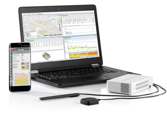
Figure 8 R&S TSME network scanner and R&S ROMES drive test software for assessing 5G NR and LTE network performance.
OUTLOOK: DSS ENHANCEMENTS IN 3GPP RELEASE 16
As shown in Figure 4, PDSCH mapping type B, as specified in 3GPP release 15, has the limitation that, at maximum, seven OFDM symbols can be allocated when this mapping type is configured. In 3GPP release 16, PDSCH mapping type B will be extended so that nine and ten symbols can be assigned to use the slot efficiently.
Another change: with release 16, the definition of multiple LTE CRS rate-matching patterns is supported for one device. The reason is that a network operator may have deployed multiple LTE carriers within a frequency band (three shown in Figure 9). These three carriers can use different bandwidths and MIMO schemes (e.g., 10 versus 20 MHz, 2 x 2 versus 4 x 4 MIMO). Even if the carriers have the same bandwidths and MIMO schemes e.g., carriers 2 and 3), they have different PCI that dictate which resource elements carry the CRS and, therefore, impact the rate-matching algorithm. 5G NR supports wider bandwidths, e.g., 50 MHz, and could use the entire channel. The definition of multiple LTE CRS rate-matching algorithms to be used by the device supports this specific deployment scenario and enables the use of DSS functionality.
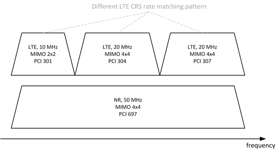
Figure 9 Multiple LTE CRS rate-matching pattern with 3GPP release 16.
SUMMARY AND CONCLUSION
DSS is the hot buzzword in the wireless industry today. It provides a service provider with the possibility to provide a coverage layer for 5G NR at low band frequencies. Besides, it allows the carrier to smoothly transition the LTE subscriber base toward 5G and roll out a standalone mode faster by avoiding the high cost of spectrum refarming or the need to acquire new spectrum licenses.
From a technology standpoint, DSS combines several sophisticated features to enable coexistence between LTE and 5G NR using the same spectral band. Therefore, it is essential to verify all the features and functionalities described above, not only in the lab by testing DSS-capable 5G handsets, but also in the network when performing drive tests for network optimization.
References
- 3GPP TS 38.101 V15.6.0 (2019-06), User Equipment (UE) Radio Transmission and Reception, Part 1: Range 1 Standalone.
- M. Kottkamp, A. Pandey, D. Raddino, A. Roessler and R. Stuhlfauth, 5G New Radio – Fundamentals, Procedures, Testing Aspects, 1st edition, Rohde & Schwarz, 2019.
- 3GPP TS 38.211 V15.6.0 (2019-06), Physical Channels and Modulation (Release 15).
- 3GPP TS 38.423 V15.4.0 (2019-07), NG-RAN, Xn Application Protocol (XnAP) (Release 15).