In Part 1, a highly stable computer-controlled K-Band frequency synthesizer is demonstrated using a tunable optoelectronics oscillator (OEO). LabVIEW software control of a modular rack-mountable frequency synthesizer is achieved from 16 to 24 GHz. A narrowband computer-controlled filter is realized using a broadband YIG filter combined with a narrowband, optically-tuned transversal filter. A forced self-injection-locked phase-locked loop (SILPLL) technique is employed to suppress side-modes generated in OEOs, caused by the long fiber delay lines, and further reduce the oscillator phase noise, reaching an estimated 12 fs timing jitter. Computer control of this SILPLL OEO is demonstrated by achieving both linear chirp (FMCW) and pseudo-random frequency hopping. In Part 2, future generations of the forced SILPLL-based OEO are introduced based on integrated optoelectronics. A Si photonics OEO design is presented using an optical phase modulator in place of the conventional optical intensity modulator, by employing a Sagnac loop as a phase modulation (PM) to intensity modulation (IM) convertor. One hundred percent PM sensitivity improvement is achieved by using a 1D photonic crystal superstrate to lateral electro-optic (EO) polymer-based PM. A forced SILPLL K-Band synthesizer using this improved PM is modeled with estimated phase noise of −148 dBc/Hz at an offset frequency of 10 kHz from a 20 GHz signal. A compact multi-mode laser is also developed, where forced oscillation achieves a clean intermodal oscillation frequency at X-Band, with a phase noise of −98 dBc/Hz at 10 kHz offset. This can be extended to K-Band.
High frequency oscillators are important for high speed data transmission. Forced oscillation has been used as a technique1-3 to stabilize oscillators, and various optical distribution techniques have been reported for stabilization of remotely located oscillators using an external frequency reference.4-8 The OEO is a new category of oscillator, based on energy storage using long optical delay lines to achieve high frequency stability.9 This structure has been widely employed for high frequency oscillators because of its high spectral purity,10 and it has been extended to 50 GHz.11 One of the challenges encountered with OEOs is the temperature sensitivity of long fiber-optic delay lines,12 which can be improved by employing passive temperature compensation using special hollow-core photonic crystal fibers (HC-PhC),13 resulting in both short- and long-term frequency stability.14 Forced oscillation techniques help to reduce the oscillation side-modes.15 Using an injection-locked phase-locked loop (ILPLL) improves phase noise close to the carrier, reduces pull-in time, enhances the locking and tracking ranges over the standard IL or PLL and reduces prime power and reduces space compared to a multiplier chain.16
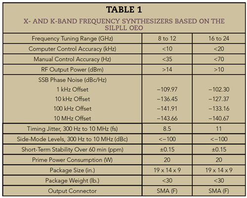
Self-forced oscillation is an approach employed in X- and K-Band frequency synthesizers17-19 without any external frequency reference, using integrated concepts of self-IL20 (SIL) or self-PLL21 (SPLL) for improvement in phase noise, both close to and far from the carrier. Oscillation side-modes are also suppressed using multiple loops with anharmonic or non-harmonic delays. The concept of SIL and SPLL are combined as SILPLL for demonstrated improvement in close-in phase noise of dielectric resonator oscillators22 and its significant side-mode suppression, which has led to low timing jitter.23 Part 1 of this article24 reviewed the design implementation and testing of a 19 in. rack-mountable, computer-controlled K-Band frequency synthesizer with high frequency resolution, using a Mach Zehnder modulator (MZM) SILPLL OEO with a YIG filter combined with an optical transversal filter. The synthesizer achieved extremely narrowband frequency selection, with operation at either X- or K-Band using bias voltage control. The performance of the X- and K-Band OEO synthesizers is summarized in Table 1.
Part 2 of this article discusses straightforward changes that reduce the size and cost, which also improve the environmental sensitivity of the synthesizer. Building on these, innovations are explored using custom integration of the SILPLL in various degrees to implement the OEO. The first step to reduce the size of the frequency synthesizer is to use alternative commercial computer-controlled power supplies and integrate the fiber laser and fiber amplifier modules. The innovations adopts Si photonics integration to convert the optical IM to a PM that is DC bias free and less sensitive to the pyroelectric and piezoelectric properties of the optical modulator. The design employs EO polymer-based phase modulators24-26 implemented with a Si photonics Si BiCMOS topology. Incorporating a photonic crystal (PhC) slow light structure to the PM25-26 leads to a nonlinear dispersive group velocity that enhances modulation sensitivity. Realization of the PM-based OEO employs PM to IM using a Sagnac loop.27-29
The simulated results for a future generation K-Band synthesizer using a SILPLL OEO show improved phase noise. The improved modulation efficiency reduces the noise figure of the fiber-optic delay lines, which in turn reduces the close-in phase noise of the OEO. A low cost, compact and stable OEO system is proposed using the intermodal oscillation output of an integrated multi-mode laser.30-32 Experimental results of this chip-level intermodal oscillator demonstrate the forced oscillation performance. The roadmap to a fully integrated IC using high Q-factor annular resonators as optical delay elements is discussed.
SIZE REDUCTION AND FREQUENCY EXPANSION
In Part 1 of this article,24 the design and implementation of a K-Band frequency synthesizer using OEO techniques were reported. Even though the prototype synthesizer shows great frequency stability, size, weight and frequency coverage compared to other commercially available electronic or optoelectronic synthesizers, the design can be further improved. In the implementation described, most of the physical space and weight in the box were from the Agilent power supply. This supply can be replaced with a compact AC-DC convertor module from XP Power (PBM200PQ05-C), with the size of the new supply only 10 in. x 6 in. x 2.25 in. - only a quarter of the size of the Agilent supply. The weight of the new unit is 1.83 lbs, a reduction of 90 percent.
The erbium-doped fiber amplifier (EDFA) can be integrated and placed inside the OEO box. In the initial design, the EDFA from Shandong Wanshuo Optoelectronic Equipment Co. contained two power supply modules for redundancy, one a backup to ensure reliable performance. An EDFA with only a single supply, a mother board for control and the other components would reduce the size to approximately half of the original Agilent power supply. This new EDFA would easily fit with the compact power supply module, yielding a total weight saving of about 18 percent and a size reduction of 20 percent. The revised system using modular components would occupy a total volume of 1200 cubic in., with the computer-controlled power supply and EDFA consuming 470 cubic in. The overall weight of the new design will be under 25 lbs, and the system can be integrated in a single housing compatible with 19 in. rack mounting.
Extending the frequency coverage of the synthesizer is also feasible. The first design covers 16 to 24 GHz. Because of the advantages of the OEO system and using the half-wave voltage (Vπ) of the intensity modulator, only a few components need to be updated to extend the upper frequency to 40 GHz: the photodiode, intensity modulator and RF amplifiers. For the optical modulator, the T.DEH 1.5-40-ADC from Sumitomo33 or the OC-768 from EOSPACE27 are options to extend the bandwidth to 40 GHz. An ultra-high speed photodetector from Discovery Semiconductors (DSC30S) will be suitable for 40 GHz, and low noise amplifiers from B&Z (e.g., BZ-30005000-550820-152020) covers the additional required bandwidth. With little system engineering and component replacement, the new synthesizer will operate to 40 GHz.
Si PHOTONICS SYNTHESIZER
Even though simple revisions can significantly reduce the size of the synthesizer, the sizes of the optical fiber mandrills and complex circuits limit further reduction; an integrated solution is necessary to go further. Also, the performance of the modular RF components will affect the performance above 60 GHz. An ideal realization of a high frequency synthesizer covering above 24 GHz requires integration of the optoelectronics circuitry using Si photonics.
The first step is a hybrid integrated SILPLL system33 using EO polymer-based optical modulators. To avoid the bias dependent characteristics of the MZM, an optical phase modulator design27 is considered using a Si photonics technique compatible with SiGe BiCMOS fabrication. The structure of the proposed phase modulator with 1 cm interaction length is shown in Figure 1. PMMI-CPO-1 is chosen as the optical core material (20 wt%), which has a refractive index of 1.63 and a conservative EO coefficient of 70 pm/V at 1550 nm. Norland Optical Adhesive 65 (NOA65) is selected as the cladding material; it has a refractive index of 1.51 and a loss tangent of 2.2 x 10⁻². The geometrical dimensions of the in-plane coupled microstrip (CMS) electrodes are calculated to achieve a 50 Ω characteristic impedance: t = 1.6 μm, WCMS = 94 μm, gCMS = 10 μm, hg = 40 μm, tbottom = 0.2 μm, hPhC = 0.6 μm and hbuffer = 0.2 μm.27
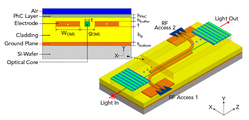
Figure 1 Electro-optic PM with integrated 1D PhC driven by in-plane CMS electrodes.
To enhance modulation efficiency, a slow light 1D PhC structure with lattice constant of 470 nm, consisting of a base material of PMMI and a substrate with 47 nm of air gaps is placed close to the optical core as a superstrate. The dispersive characteristic of the propagating light inside the optical core is affected by the slow light effect, as depicted in Figure 2. The effect is maximized when the PhC layer touches the optical core, with the optical loss a significant side-effect. The dispersive effect gets stronger as the PhC layer thickens, at the cost of increased optical loss. A combination of hbuffer of 0.6 μm and hPhC of 0.2 µm represents a compromise between the thickness of the buffer layer and height of the PhC layer. The modulator figure of merit Vπ x L and optical loss were modeled at approximately 3 Vcm and 3 dB/cm, respectively, using a commercial optical simulator, OptiBPM. Compared to a Vπ x L of 7.2 Vcm for a phase modulator without the PhC layer, the half-voltage magnitude is more than 100 percent improved.
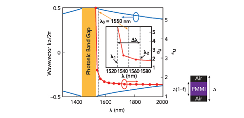
Figure 2 Photonic band structure and group index vs. wavelength for lattice constant a = 470 nm and filling fraction f = 0.1, with λ1 = 1530 nm, λ2 = 1570 nm and Δλ = 40 nm.
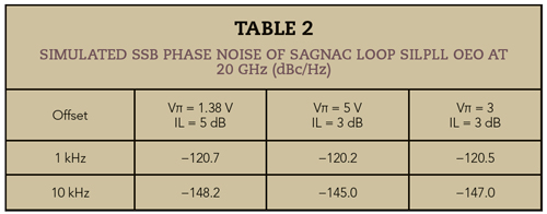
The realization of the SILPLL-based OEO is based on a Sagnac loop28 (see Figure 3), where the input light coming from the tunable laser source is fed into an optical coupler and equally divided into clockwise (CW) and counter-clockwise (CCW) paths around the loop. Both CW and CCW signals propagate through the phase modulator and travel around the other half of the loop, where only the CCW propagating signal is phase shifted by a non-reciprocal phase shifter, because of the polarization controller. The simulated phase noise performance is better than −148 dBc/Hz at 10 kHz offset using this SILPLL architecture29-30 (see Table 2).
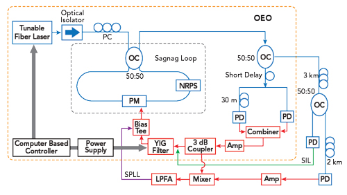
Figure 3 PM-based SILPLL K-Band OEO synthesizers (outer dashed box) with Sagnac loop, optical/RF paths (blue and red) and SPLL/SIL (purple and green).