
There has been a long-standing argument that microwave and mmWave vacuum electron devices (VED) - known as traveling wave tubes (TWT), TWT amplifiers (TWTA) or microwave tubes (MWT) - are an obsolete technology almost completely superseded by solid-state power amplifiers (SSPA). Throughout the larger electronics industry, tube transistors have, for the most part, been replaced by solid-state transistors. However, within the microwave and mmWave industries, the extremely high-power capability at higher frequencies, relatively compact size and steadily increasing reliability of VEDs has maintained a nearly $1 billion market despite the opinion that VEDs are large, cumbersome, complex, expensive and unreliable solutions.1
VEDs are essential devices in many space, aerospace, military, electromagnetic interference (EMI), electromagnetic compatibility (EMC), weather and radar applications. Though the common opinion may be that VEDs are obsolete devices, now only used in legacy applications and long-standing contracts, this is far from true. SSPA technology essentially replaced VEDs in commercial, low power and low frequency applications decades ago. However, even with the advent of “high-power” GaN power amplifiers (PA), SSPA technologies have yet to supersede TWTAs for extremely high-power levels and at high frequencies (i.e., mmWave). This article provides an update on the current state of VEDs, specifically TWTAs, how they compare with available SSPA solutions and why this “legacy” technology is still being actively developed and deployed.
TWTA Overview
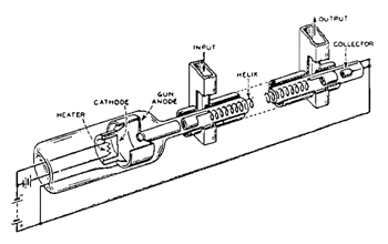
Figure 1 Traveling wave tube cutaway. Source: Tele-Tech magazine.2
A TWT operates by generating an electron beam from an electro-optical system consisting of an electron gun, electrodes, delay line and a collector of the electron beam (see Figure 1). The electrodes act to focus and accelerate the electron beam. A heater is used to ensure that the electron beam cathode reaches the desired operational temperature to generate electrons. There are two RF ports: an input port, at the start of the delay line near the beam generator, and an output port, at the end of the delay before the collector. With reflections within the TWT from the RF input and output ports, a microwave absorber is added to reduce the reflections and mitigate self-excitation. Hence, it is important to ensure that the RF ports are terminated with a matched load.
A driver amplifier and attenuator combination are often used to ensure that the RF input to the TWTA is at the desired signal level. Several additional inputs are needed for it to operate, including a high voltage power supply, heater, low voltage power supply, driver amplifier power supply and a control and monitoring circuit to prevent failure (see Figure 2). Given the system complexity and number of critical inputs, many consider TWTAs to be large, cumbersome and expensive, with a low lifespan and high maintenance. Though this may be true in the most extreme applications at the edge of TWTA technology and performance, this is not true for most applications that use TWTAs, which have been improving for decades.
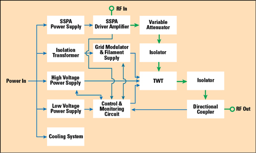
Figure 2 Generic TWT amplifier block diagram showing RF signal path (green).
Modern TWTAs vs. SSPAs
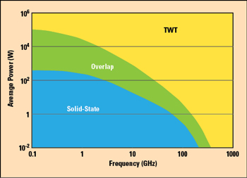
Figure 3 Power/frequency trade space between TWT and solid-state power amplifiers.3

Figure 4 Generic solid-state power amplifier block diagram showing RF signal path (green).
SSPAs have steadily been integrated into more system designs, yet there are still regions of power and frequency where TWTAs dominate and likely will for some time (see Figure 3). The benefits of SSPA technology are derived from its small footprint, high-power density, large process technology and ability to be integrated into compact assemblies. However, these factors create additional cooling challenges at higher power levels and frequencies, where the resistive losses of the lower operating voltage and higher current of the semiconductors, with the associated resistive losses in the conductors, are much higher than at lower frequencies. Hence, there is a practical power versus frequency limit for SSPAs, where the cost benefit of using SSPAs diminishes compared to TWTAs. This region is typically toward the hundreds of Watts of output power at microwave frequencies and beyond several Watts at mmWave.
TWTAs typically have higher operating voltage, which mitigates the resistive losses at higher frequencies. Therefore, TWTAs can deliver much higher pulsed peak and continuous wave (CW) power. In these higher power regimes, it is also likely that TWTAs are comparable, if not superior, in power efficiency, due to the increased power combining losses for the more complex SSPA assemblies.
To reach higher power, it is common to combine several SSPAs. Figure 4 shows a block diagram of an N-way combined SSPA, with the accompanying interconnect, power combining and accessory components. These complex assemblies, though viable in some cases, introduce greater system complexity and additional failure modes. They typically reduce overall efficiency (from power combining insertion loss and matching the individual PAs), degrade noise figure and create a substantial cooling challenge. As each of the components in a compound SSPA are not broadband, designing and fabricating a high-power SSPA with wide bandwidth may require substantial engineering and custom solutions.
Compared to TWTAs, the reliability of SSPAs is commonly considered to favor SSPAs; however, this is not necessarily the case at high-power levels and high frequencies. In the past, largely due to the state of fabrication technology and poor operating practices, it was rare yet common enough for the tubes in TWTAs to only last a couple of years. Recently, advances in fabrication technology, tooling and materials - which also benefit SSPAs - have led to tubes rated to nearly 20,000 hours of operation, yielding a usable lifespan of 8 to 10 years. This lifespan is comparable to SSPA technology, although SSPAs typically do not require maintenance throughout their lifespan. This benefit could be offset in a highly integrated SSPA, where replacing a failed internal amplifier may be impractical; however, replacing a failing tube in a TWTA is a procedure accounted for in the maintenance plan. Regardless of the technology, SSPA or TWTA, for the system to be reliable, backup units are needed.
SSPA technology has advanced over the years, yielding amplifiers that reach tens of kW of output power and operate over 100 GHz. However, SSPA solutions reaching these extremes are generally expensive, custom and may not meet the reliability or performance standards required by legacy and emerging applications. VEDs such as TWTAs are often the only viable solution for high-power, high frequency and ultra-wideband applications.
SSPA technology typically uses mass produced solid-state devices that are not readily customizable. Some customization can be done on the amplifier pallet and with additional circuitry, but the performance limits of the amplifier are constrained by the solid-state transistors and the underlying fabrication processes. With TWTAs, a significant amount of customization is available with the design and tuning of the amplifier system. Applications that require very specific performance criteria rely on TWTAs, especially for use cases that require extreme CW power, frequency, bandwidth, pulse repetition frequency (e.g., MHz PRFs), long duty cycle pulses and high peak pulse power.
The health of the MWT in a TWTA amplifier is the greatest liability of the system. Poor design, care and use of a TWTA can dramatically reduce the lifespan of a MWT and lead to accelerated degradation. This is a common challenge with VEDs and MWTs, as matching MWTs is difficult, and each MWT requires slightly different input characteristics for optimal operation. Hence, an area of ongoing development is more intelligent high voltage power supplies that can adjust performance over time to optimize the output power of the TWTA as a tube ages. With intelligent heater systems, a TWTA may become easier to use with lower maintenance.
Table 1 compares the characteristics of TWTAs and SSPAs.

Trends Driving TWTA Growth
Several industries rely on VEDs for high-power microwave and mmWave applications, such as radar, aerospace, weather and SATCOM. As well as having legacy applications that require upgrades, new applications demand advancements in the design and performance of TWTAs. Though some may believe that TWTAs only serve legacy applications, several key trends in microwave and mmWave applications are driving new use cases and demands of TWTA technology. These include terrestrial communications, such as 5G testing and mmWave backhaul, and SATCOM, moving to upper microwave and mmWave frequencies. This growing communications market is creating interest in moving radar systems to higher frequencies to avoid interference.
With more applications moving to higher frequencies, EMI and EMC testing requires instruments that can operate at high-power with high quality over very broad bandwidths. Most of these new applications require microwave and mmWave power sources, high-power test equipment - even high-power amplifiers in the end product. The recent opening of additional license-free spectrum at V-Band (57 to 71 GHz) has created the need to test these new applications at frequencies and power levels typically beyond the capability of SSPAs. Outside of the usual markets, the availability and understanding of microwave and mmWave technology is providing new opportunities for scientific research, such as linear accelerators and RF propulsion for spacecraft.
Summary
VEDs, such as TWTAs, are still very much in use for applications with extreme power and frequency demands. Though often considered outdated, TWTAs are being used in new and leading technology applications, including 5G, mmWave backhaul, SATCOM, high-power and high frequency testing and scientific research. It is likely that tubes will continue to be the only solution that provides high-power at microwave and mmWave frequencies with GHz of bandwidth for many years.
References
- “ABI Research Finds Microwave Tube Market Still Strong at Over $1B for 2018,” Microwave Journal, January 16, 2019, www.microwavejournal.com/articles/31649.
- F. Loomis, “Bell System Plans for Broadband Network Facilities,” Tele-Tech Magazine, Caldwell-Clements Inc., Bristol, CT, Vol. 12, No. 4, April 1953.
- V. Kesari and B. N. Basu, “High Power Microwave Tubes: Basics and Trends, Volumes 1 and 2,” January 2018, Morgan & Claypool Publishers.