
A two-part article is presented describing a highly stable computer-controlled K-Band frequency synthesizer using a tunable optoelectronics oscillator (OEO). The first part describes LabVIEW control of a rack-mountable frequency synthesizer covering 16 to 24 GHz. A narrowband computer-controlled filter is realized using a broadband YIG filter combined with a narrowband, optically-tuned transversal filter. A forced self-injection locked phase-locked loop (SILPLL) technique is employed to suppress side-modes generated in OEOs because of long fiber delay lines, which reduces the oscillator phase noise to an estimated 12 fs timing jitter. Computer control of this SILPLL OEO is demonstrated with linear chirp (FMCW) and pseudo-random frequency hopping. Future generations of the forced SILPLL OEO will use integrated optoelectronics. In Part 2 of the article, compact OEO solutions based on designs compatible with Si photonics are described.
High frequency oscillators are important for high speed data transmission. Forced oscillation is a technique where the oscillation frequency can be stabilized using the concept of injection locking (IL)1-2 and phase-locked loops (PLL).3-5 Distribution of a highly stable, low phase noise external frequency reference is employed to force the oscillator to lock to the clean phase noise characteristics of the reference. The indirect optical injection locking6-7 has been applied to distributed microwave8 and mmWave oscillators9-14 for optical control of large phased-array antennas for radar and communications.15-18 The analytical modeling of injection locked oscillators has been developed based on parametric oscillation19-24 to achieve low phase noise from various frequency references. The combination of both injection locking with a phase-locked loop is proposed as an injection locked, phase-locked loop (ILPLL) forced stabilization process, and its superior performance is experimentally demonstrated. A number of oscillator topologies25-28 are used for efficient front-end operation of a low phase noise, high frequency stability28 low free-running phase noise oscillator, combined with mixing conversion gain with high dynamic range. Prime power and space saving are also achieved.26-27 It is feasible to combine mixing with oscillation and phase shifting17 as a very elegant solution for electronically scanned phased-array antennas for communication and remote sensing.
The category of oscillators based on long optical delay lines to provide high frequency stability29 is known as OEO.30 This structure has been widely employed for implementing high frequency RF oscillators because of its high spectral purity,31 and it has been extended to operate to 50 GHz.32 One of the challenges encountered with the OEO is the temperature sensitivity of the long fiber-optic delay lines.33 Performance can be improved by employing passive temperature compensation using special hollow-core photonic crystal fibers (HC-PhC),34 improving both short-term and long-term frequency stability.35 The broadband behavior of fiber-optic delay lines provides frequency tuning of the OEO with a large number of potential oscillation frequencies. Narrowband filters are the core part of an OEO, determining the oscillation frequency by employing extremely narrowband fixed frequency filters.33 To achieve broadband frequency tuning, YIG filter structures36 are integrated in the optical delay line,37 as reported with FET-based tunable oscillators.38 Even though the OEO can have a higher quality factor with longer fiber delay lines, multiple side-modes exist around the oscillation frequency; 5 km of fiber will have side-mode oscillations every 40 kHz. Removing them is not feasible, even using narrowband electronic filters. Coarse tuning of a wideband YIG filter36 combined with fine tuning a narrowband wavelength-tuned optical transversal filter39-43 using short delay lines or a chirped fiber Bragg grating44 provides high resolution frequency selectivity. Nonetheless, a number of side-modes persist, although forced oscillation techniques can reduce the oscillation side-modes.44
The benefits of ILPLL25 in electronic systems45 are from improvements in close-in phase noise, pull-in time and the locking and tracking ranges, compared to the standard IL or PLL, and reduced prime power and space compared to a multiplier chain. These benefits can also be achieved in oscillators without an external frequency reference, using the concepts of self-IL (SIL)46-49 or self-PLL (SPLL).50-52 They improve phase noise both close-in and far from the carrier, while oscillation side-modes are suppressed using multiple loops with harmonic delays. SIL and SPLL can be combined as SILPLL,53 demonstrating improvement in close-in phase noise of dielectric resonator oscillators54 and significant side-mode suppression, yielding low timing jitter.55
This article focuses on the development of a self-forced OEO and is presented in two parts. Part 1 discusses the design and testing of a 19 in. rack-mountable, computer-controlled K-Band synthesizer with high frequency resolution. The SILPLL OEO design uses a Mach-Zehnder modulator (MZM) and YIG filter combined with an optical transversal filter to achieve extremely narrowband frequency operation. The synthesizer employs a dual-drive modulator (DD-MZM)56 with a bias voltage dependence of either the quadrature point (Vπ/2) or pinch-off voltage (Vπ). The operating point close to Vπ/2 has higher gain, while operation at Vπ results in lower gain with second-order harmonic generation. Low phase noise is achieved over 16 to 24 GHz, with a frequency resolution of 20 kHz/pm of optical wavelength control at 1550 nm. Computer control generates both FMCW and frequency hopped operation of the synthesizer, enabling it to be used for remote sensing and secure communications applications. In Part 2 of the article, additional design innovations are described which lead to a compact OEO.57-60
SYNTHESIZER DESIGN
The block diagram of the OEO synthesizer is shown in Figure 1. A fiber laser with low relative intensity noise, the TWL-C-HP-M, is used to provide a tunable wavelength laser signal. The laser signal transmits through optical fiber delay lines and is received by high speed photodetectors (Discovery Semiconductors DSC50S) to generate an electrical signal which passes through a narrowband filter. This narrowband filter is the core of the OEO, used to select the oscillation frequency. A high Q metallic filter is the classic approach to realize a fixed frequency OEO, where mechanical adjustment of the cavity length tunes the frequency. As this approach is not suitable for computer control, a YIG filter36 is used for this synthesizer design. The YIG filter is attractive because it has a broad tuning range and can be computer-controlled. To compensate for the poorer frequency selectivity of wide-tuning YIG filters, a narrowband optical transversal filter42 is added, realized with a 30 m fiber. The YIG filter provides coarse tuning of the synthesizer, i.e., 50 MHz/mA. The highest resolution for the power supply (Keysight E3631A) in constant current mode is 1 mA, so smaller frequency steps will be provided by the transversal filter.
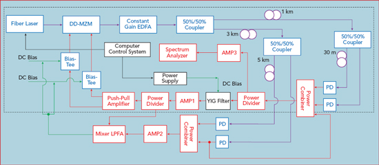
Figure 1 Detailed block diagram of the OEO system.
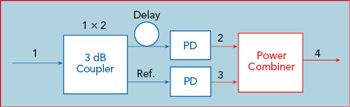
Figure 2 First-order optical transversal filter using a 3 dB splitter and combiner with an optical delay in one path.
An optical transversal filter42 can provide narrowband filtering of microwave signals; a first-order transversal filter is shown in Figure 2. An optical signal is divided into two paths, with one path the reference, the other creating the delay. This is represented by the following filter transfer function, in terms of RF frequency

where τd is the fiber delay at the fiber laser wavelength. The delay is related to the difference in length, ΔL, between the reference and delayed paths. n(λ0) is the index of refraction at the wavelength λ0.
τD is a term reflecting fiber dispersion, expressed as

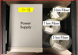
Figure 3 View of the custom fiber mandrels adjacent to the computer-controlled DC power supply.

Figure 4 View of the fiber laser source, driver and commercial YIG filter.
In Equation 3, D is the dispersion parameter in units of ps/nm/km, while Δλ is the difference between the optical source wavelength and original wavelength. The null-to-null bandwidth is around 4.5 MHz at 1550 nm. The tuning sensitivity achieved using the picometer resolution of the fiber laser is 20 kHz/pm. Using computer control, after setting the desired frequency, the frequency setting process terminates when the difference between the desired frequency and the detected frequency is smaller than half the fine tuning resolution, approximately 10 kHz; the final output is then shown on the LabVIEW display.
In addition to the optical frequency selectivity, SIL,49 SPLL52 and the combination SILPLL53-54 is used to reduce the synthesizer’s phase noise, both close-in and far from the carrier frequency. The block diagram outside the dotted area of Figure 1 depicts the single delay loop SIL49 and dual optical delayed DSPLL.52 There are two paths for the modulated signal after the MZM: one is used as the main loop of the OEO, with the other loop further split into two paths of 3 and 8 km, which are used as dual phase-locking signals. The combined phase-locking signal drives a PCB board containing the “Mixer LPFA” block shown in Figure 1. A double balanced mixer is integrated on the same board with a lowpass filter amplifier, realized with op-amp circuits, which serves as the phase detector and lowpass filter portion of the PLL. The phase error of the OEO main loop is compared with the dual delay lines of the PLL, and the phase error signal is fed back to the bias port of the MZM. The self-injection locking signal takes advantage of the PLL path and shares the same fiber used in the SPLL path. The 3 km SIL signal is split from one PLL signal and directly injected into the output of the metallic cavity. The injected power level is given by ρ = √(Pi/PO ), where Pi is the injected signal power and PO the OEO power level. A higher value of ρ results in better suppression of the phase noise far away from the carrier.

Figure 5 View of the RF and fiber-optic components on the third level of the synthesizer housing.
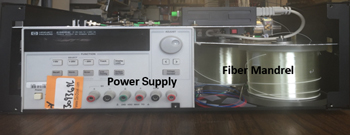
Figure 6 Front view of the OEO synthesizer, showing the power supply (left), 1 and 5 km fiber mandrels, laser driver and other components.
Figure 7 Complete SILPLL OEO system.
After successfully demonstrating the synthesizer on a lab table, it was integrated into a 19 in. rack for practical use. The assembly detail is shown in the following views, where the step-by-step assembly of the system reflects the block diagram shown in Figure 1. The first floor of the synthesizer box (see Figure 3) comprises three fiber mandrels and the DC power supply. The topside of the cover over the mandrels and power supply contains the laser driver, laser and YIG filter (see Figure 4), commercial products from Optilab and Teledyne. A third-level assembly integrates the remaining RF and fiber-optic components, mounted on a sheet metal cover and connected using coaxial cables or optical fibers (see Figure 5); this sheet is placed on top of the second level. Figure 6 shows a front view of the three levels, with all the circuits packaged within the overall height of the enclosed box, covered with metal on the front, top and back sides, with venting to help dissipate the heat of the power supply. A commercial Er doped fiber amplifier (EDFA) is mounted on top of the OEO box and shares the screws with the OEO box for stabilization and to maintain good connection between the EDFA and OEO unit (see Figure 7).
The synthesizer has DB9 and RS232 interface ports for computer control of the laser source and DC power supply. The program for computer control, developed using LabVIEW 2018, controls the output wavelength of the fiber laser and the current bias of the YIG filter to realize the narrowband frequency selection (see Figure 8). To set the operating frequency, users type the desired value into the graphical interface shown in the figure. Using a look-up table, the program iteratively changes the current bias of the YIG filter and wavelength of the fiber laser, corresponding to coarse and fine tuning, respectively. The desired frequency is achieved in under 15 seconds. The time for frequency acquisition reflects the iterative process to attain the proper YIG filter bias current and fiber laser wavelength, given the extremely narrowband bandpass characteristics of the cascaded YIG and optical transversal filters. This settling time can be reduced using a custom power supply and controllers.
The measured phase noise of the OEO system is shown in Figure 9. The synthesizer outputs are measured at steps of 2 GHz from 16 to 24 GHz, demonstrating operation across all of K-Band. The measured phase noise is −105 dBc/Hz at 1 kHz offset from the carrier and −130 dBc/Hz at 10 kHz offset. The long-term stability of the 19 in. unit was evaluated, recording a 4.5 kHz frequency shift over 1 hour. The estimated rms timing jitter of the synthesizer is under 10 fs, which can be reduced using SILTPLL.54-55 A contributor to the phase noise is the 1/f noise of the amplifier; this can be improved using a SiGe HBT amplifier rather than GaAs PHEMT,61-62 and with proper selection of the operating conditions of the transistors.63
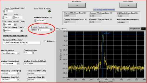
Figure 8 LabVIEW control interface for the synthesizer.
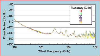
Figure 9 Measured phase noise of the K-Band OEO system with 16 to 24 GHz carriers.
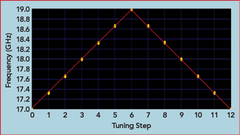
Figure 10 Linear frequency sweep using the LabView control program.
Computer control of the K-Band synthesizer was demonstrated by generating a sequence of frequencies for several applications. Figure 10 shows the LabVIEW routine for linear frequency modulation, representing a practical FMCW radar application. The program steps the frequency from 17 to 19 GHz with six linear steps, then steps back at the same rate to 17 GHz. Figure 11 shows a pseudo-random frequency hopped pattern representing a frequency hopped communication system; the pattern was designed to spell DREXEL after 61 steps. These examples demonstrate the frequency synthesizer’s tuning capability, low close-in phase noise and computer-controlled frequency selection.