
The thermal conductivity of the RFPA PCB is calculated by considering the system in a vacuum. A vacuum environment ensures that heat transfer from the hot PCB-TIM-Al plate system is solely through thermal radiation, as encountered by the spacecraft in deep space. For the analysis, a 46 cm x 46 cm x 46 cm volume at 20°C and an aluminum mounting plate of 9 cm x 5 cm x 0.635 cm were used. Only one side of the aluminum plate was assumed to radiate energy, and its emissivity was assumed constant at all temperatures and IR wavelengths. Sixteen vias were included to aid heat transfer from the RFPA MMIC through the PCB to the TIM. Emissivities of 0.09 and 0.72 were used. A higher emissivity value of 0.72 was chosen to represent a coating on the CubeSat face where the RFPA PCB is attached, while the rest of the CubeSat sides were assumed to have an emissivity of 0.09. For a given thermal power sourced at the RFPA, energy radiated by the system in vacuum environment was calculated from
Q(J) = εAFσ(T14 – T24)
where Q(J) is the heat energy radiated from the system, ε the emissivity of the system, A the area that aids the thermal radiation, F the view factor (ranging between 1 and 2), σ Boltzman’s constant, T1 the temperature of the heat source (i.e., the Al plate in this system) and T2 the temperature of the heat sink (i.e., the vacuum environment).
The material specification for the hot PCB-TIM-Al plate system was analyzed using thermal desktop software. Figure 3 shows the materials stack, including the RFPA MMIC. The RFPA, the primary source of thermal power, was modeled as a resistor with equivalent power generation. The sink for the thermal power was chosen to be one of the aluminum faces of the CubeSat, which radiates the heat energy into a vacuum. The source of thermal power is at the bottom because the RFPA PCB will be mounted inverted to the top face of the CU-E3 CubeSat to achieve the most effective thermal radiation. Because the top face of CU-E3 radiates to cold space, it is the best location to mount the RFPA. Analytic and software analysis of the thermal system gave similar results for different operational scenarios and different emissivities. Table 4 shows the RFPA heat load temperatures determined using both methods. Along with the RFPA PCB placement, the software analysis determined the effect of the PCB area on PCB temperature, and Figure 4 shows the change in temperature as the area is increased. A significant drop from approximately 450ºC to 75ºC was predicted as the area was increased from approximately 5 to 45 cm2.
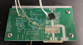
Figure 5 PCB with dummy heat load in place of the RFPA, mounted to an aluminum plate and instrumented with thermocouples.
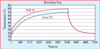
Figure 6 Measured RFPA PCB temperature vs. time.
Desktop simulation was also used to estimate the maximum transmit time of the communication system based on the RFPA PCB’s thermal dissipation. A more complex model of the entire CubeSat was created, including the helio-centric trajectory of the spacecraft. The analysis found a cold PCB in the off state quickly reaches a temperature of approximately 67ºC once the RFPA is turned on. The PCB reaches a temperature of about 77ºC within 40 minutes, which is below the maximum operating temperature of the MMIC. Once turned off, the PCB takes about 60 minutes before reaching the steady state temperature of the environment.
RFPA PCB TESTING
Benchtop tests were performed to measure the effectiveness of the FujiPoly XR-Um TIM. A resistor of equivalent power handling capacity (greater than 8.7 W) was used as a heat source in place of the RFPA. Two thermocouples connected to the data acquisition system were attached to the system, one to the top of the RFPA PCB, another to the aluminum plate underneath the TIM (see Figure 5). Power supplied to the resistor was varied and temperature readings recorded. Figure 6 shows one set of temperature versus time readings from the thermocouple connected to the top of the PCB and the thermocouple connected to the aluminum plate. A heat load of approximately 2 W was used. Within 85 minutes, the PCB temperature reached a peak of 60ºC, and the aluminum plate temperature reached 55ºC. The 5ºC difference between the two surfaces demonstrates the effectiveness of the PCB design and the FujiPoly XR-Um TIM for thermal power dissipation. When cooled, both the PCB and aluminum plate followed a similar trajectory to reach room temperature over 43 minutes.
SUMMARY
The design, simulation and testing described in this article establish a baseline to predict the thermal performance of the RFPA PCB for deep space communications, providing a better understanding of performance drivers such as RFPA efficiency, PCB design, PCB size and the choice of TIM.n
Acknowledgments
The author would like to thank Scott Palo for his comments and Chris Harnack for generously letting him use the simulations and test results described. The author would also like to thank Frank Barnes for helpful conversations on heat conductions techniques and Chinmayi Dhangekar and James Mason for graciously sharing the results shown in Figure 4.
References
- G. K. Noreen, A. L. Riley and V. M. Pollmeier, “Small Deep Space Mission Telecommunications,” Proceedings of the 8th Annual Small Satellite Conference, August 1994.
- T. Svitek, “$3M Planetary Missions: Why Not? - Consideration of Deep-Space Spacecraft Mission Requirements,” Proceedings of the 12th Annual Small Satellite Conference, August 1998.
- M. Kobayashi, “Iris Deep-Space Transponder for SLS EM-1 CubeSat Missions,” Proceedings of the 31st Annual Small Satellite Conference, August 2017.
- R. Funase, T. Inamori, S. Ikari, N. Ozaki, S. Nakajima, K. Ariu, H. Koizumi, S. Kameda, A. Tomiki, Y. Kobayashi, T. Ito and Y. Kawakatsu, “One-Year Deep Space Flight Result of the World’s First Full-scale 50 kg-Class Deep Space Probe PROCYON and Its Future Perspective,” Proceedings of the 30th Annual Small Satellite Conference, August 2016.
- J. Cockrell, K. Twichell, J. Hanson, M. Roman, E. Eberly and D. Klumpar, “NASA Cube Quest Challenge: Citizen Inventors Advanced CubeSats into Deep Space on 2018 EM-1 Mission,” Proceedings of the 30th Annual Small Satellite Conference, Logan, August 2016.
- E. Hyde and J. Cockrell, “NASA’s Cube Quest Challenge: Ground Tournament 4 Results and Technology,” Proceedings of the 31st Annual Small Satellite Conference, August 2017.
- J. S. Sobtzak, E. G. Tianang, V. Joshi, B. M. Branham N. P. Sonth, M. DeLuca, T. Moyar, K. Wislinsky and S. E. Palo “A Deep Space Radio Communications Link for Cubesats: The CU-E3 Communication Subsystem,” Proceedings of the 31stAnnual Small Satellite Conference, August 2017.
- C. Chu, H. Huang, H. Z. Liu, C. H. Lin, C. H. Chang, C. L. Wu, C. S. Chang and Y. H. Wang, “A 9.1–10.7 GHz 10 W, 40 dB Gain Four-Stage PHEMT MMIC Power Amplifier,” IEEE Microwave and Wireless Components Letters, Vol. 17, No. 2, February 2007, pp. 151–153.
- S. L. G. Chu, A. Platzker, M. Borkowski, R. Mallavarpu, M. Snow, A. Bowlby, D. Teeter, T. Kazior and K. Alavi, “A 7.4 to 8.4 GHz High Efficiency PHEMT Three-Stage Power Amplifier,” IEEE MTT-S International Symposium Digest, Vol. 2, June 2000, pp. 947–950.
- R. Wang, M. Cole, L. D. Hou, P. Chu, C. D. Chang, T. A. Midford and T. Cisco, “A 55% Efficiency 5 W PHEMT X-Band MMIC High Power Amplifier,” IEEE GaAs IC Symposium Digest, November 1996, pp. 111–114.
- M. Cardullo, C. Page, D. Teeter and A. Platzker, “High Efficiency X-Ku Band MMIC Power Amplifiers,” IEEE MTT-S International Symposium Digest, Vol. 1, June 1996, pp. 145–148.
- A. P. de Hek, P. A. H. Hunneman, M. Demmler and A. Hulsmann, “A Compact Broadband High Efficient X-Band 9 W PHEMT MMIC High-Power Amplifier for Phased Array Radar Applications,” IEEE GaAs IC Symposium Digest, October 1999, pp. 276–280.
- S. E. Palo, D. O’Connor, E. DeVito, R. Kohnert, G. Crum and S. Altunc, “Expanding CubeSat Capabilities with a Low Cost Transceiver,” Proceedings of the 28th AIAA Small Satellite Conference, August 2014.
- S. E. Palo, “High Rate Communications for CubeSats,” Proceedings of the IEEE International Microwave Symposium, May 2015.
- S. Altunc, O. Kegege, S. Bundick, H. Shaw, S. Schaire, G. Bussey, G. Crum, J. C. Burke, S. Palo and D. O’Connor, “X-Band CubeSat Communication System Demonstration,” Proceedings of the 29th AIAA Small Satellite Conference, August 2015.