
TTD BEAMFORMING
As shown in Figure 2, with a uniform linear array, the incident wavefront at an angle θ results in a delay (τ...Nτ) for the signals arriving at different elements. This delay causes the antenna array to have a pattern depending on the frequency. To have a flat pattern over the desired frequency range, the antenna’s coherent bandwidth should be greater than the bandwidth of the signal. This implies that Nτ<<Ts, where TS is the duration of the symbol. This condition requires the system to have the capability to perform delay compensation to coherently combine signals. Figure 3 shows the beam squint resulting from the frequency selectivity of an array, which does not occur with TTD beamforming. The relationship Nτ<<Ts indicates the antenna’s delay spread can become very large relative to symbol duration if either the antenna is very large (N) or the symbol duration is very small (TS), i.e., the bandwidth is very large. This point is illustrated in Figure 4.
SatixFy has developed the industry’s first TTD DBF in a form that is efficient in power and cost (see Figure 5). The Prime ASIC has a modular and flexible architecture supporting real-time reconfiguration, online calibration and the scalability to build large antennas. Prime digitizes the signal at each antenna element with high speed analog-to-digital converters (ADC) and digital-to-analog converters (DAC), processing more than 2 Tbps data rates. Prime connects to RFFEs containing the RF transceivers via a high bandwidth I/Q interface. Within each DBF, the ADCs and DACs are connected to high-resolution digital phase shifters and digital delay circuits which implement TTD to avoid beam squints, enabling wideband signal transmission and reception. The DBF chips are connected to each other via a high speed digital serial bus (SERDES), which enables a highly integrated, controllable and scalable antenna system. The key features of the Prime DBF are:
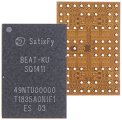
Figure 7 SatixFy Beat Ku-Band front-end.
- Over 1 GHz instantaneous signal bandwidth.
- Multi-beam capability: up to 32 beams with independent phase, gain and delay control for each beam (see Figure 6).
- Equalization/pre-equalization and digital predistortion for each beamformer chain.
- 2 GHz analog baseband interface.
- Tight integration with SatixFy’s Sx3000 modem via SERDES interface.
- Support for an external modem with an L-Band interface.
- Very high speed beam tracking and beam steering.
- Linear and circular polarization control.
- Self-calibration with internal synchronization engines.
- Antenna control integrated with the Sx3000 modem.
- Power saving modes and configurations tailored to the application.
RF Transceiver
A companion to the Prime DBF, Satixfy’s first-generation RFFE is a Ku-Band RFIC which links the Prime’s I/Q signals with the Ku-Band antenna elements (see Figure 7). Called Beat, the RFFE integrates the transmit driver and power amplifier, transmit up-converter, receive low noise amplifier, receive down-converter and antenna polarization control, either linear or circular (see Figure 8). A single Beat supports four Ku-Band antenna elements operating in half-duplex mode.

Figure 8 Block diagram of a single element, circularly polarized Tx (a) and Rx (b).
Figure 9 shows the block diagram of a fully integrated ESMA system composed of the Prime DBF, Beat RFFE and the antenna panel. The Prime DBF at the heart of the electronically-steerable antenna is connected to the Beat RFFE via an analog I/Q interface and to the Sx3000 modem via high speed SERDES. This level of integration enables a highly configurable antenna supporting different applications. Within this architecture, the DBF is band-agnostic, meaning to build phased array antennas for different satellite (Ku-, Ka- or X-Band) or 5G (sub-6 or 28 GHz) bands, only the RFFE and antenna panel need to be modified. The backbone of the BFN remains the same, greatly simplifying antenna designs for different applications and frequency bands. For phased array antennas at VHF and UHF, Prime can be used with an LNA and PA without up- or down-converters.
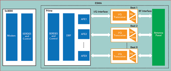
Figure 9 System architecture.
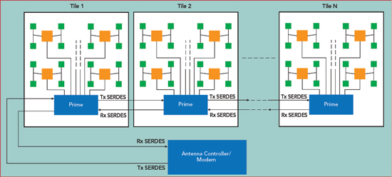
Figure 10 Tiled ESMA to increase aperture size.

Figure 11 Ku-Band 256-element ESMA.
The modular architecture of the ESMA enables it to be scaled to larger arrays by tiling. An example is shown in Figure 10, where a single tile of 32 antenna elements requires eight Beats and one Prime. The tiles are daisy-chained via high speed SERDES, which provides both data and the control plane to and from the antenna controller.
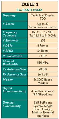
SatixFy recently introduced the world’s first fully digital 256-element ESMA for Ku-Band SATCOM (see Figure 11 and Table 1). The ESMA antenna can serve both as a standalone IoT terminal or a building block for a larger array. The antenna is a single board design with a shared aperture antenna (Rx and Tx), operating from 11 to 12 GHz for Rx and 13.75 to 14.5 GHz for Tx. The 256-element ESMA comprises eight Primes daisy-chained and 64 Ku-Band Beats. The antenna can simultaneously point, track and manage multiple beams with multiple polarizations. Figure 12 shows the antenna radiation patterns, measured in an anechoic chamber.
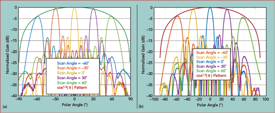
Figure 12 Measured 256-element ESMA H-plane radiation patterns vs. scan angle: Tx at 13.75 GHz (a) and Rx at 11.7 GHz (b).
ApplicationS
The flexible ESMA architecture enables low-cost, adaptive and steerable antenna system with low weight and power consumption. This makes this system viable and attractive for various applications:
IoT
In rural areas, satellites can provide the missing coverage to connect sensors and other entities to the cloud, such as sensors for agriculture, water metering, weather, petrol and gas metering. The ESMA enables compact, low-cost and low-power IoT antennas that can automatically search, acquire and track satellites. Advantages of the ESMA include eliminating bulky mechanical structures and self-installation and tracking, which significantly reduce installation cost and enables mobile applications on vehicles, ships, aircraft and drones. The small antenna size is feasible using appropriate waveforms,1-2 making it possible to communicate at very low SNR.
Broadband Communications for Land, Maritime and Aeronautical Applications
High capacity GEO networks and new constellations of LEO and MEO satellites will help serve the demand for broadband access, both for fixed terminals in remote areas and SOTM applications. During the past decade, the demand for broadband connectivity and inflight entertainment on commercial airlines has demonstrated the need for low drag and highly reliable antenna systems, making a conformal antenna based on ESMA a good solution. The simultaneous multi-beam capability enables simultaneous connectivity with multiple satellites and make-before-break connections to ensure seamless connectivity - particularly when switching beams with LEO satellites at high speed. These same benefits extend to land mobile and maritime applications, where ESMA based SATCOM links can co-exist with terrestrial wide area communications. The ESMA can be scaled according to the required link budget, physical size, weight and power consumption constraints of the platform.
5G Fixed Wireless Access
The jump in 5G data rates, compared to 4G, relies on smart antennas with multiple, wideband, directive beams. ESMA’s beamforming capability can increase spectrum utilization by up to two orders of magnitude. The high precision phase shifters and TTD in the DBF makes it suitable for the both mmWave and sub-6 GHz arrays. The ESMA’s flexibility enables dynamically reconfiguring the beams, combined with 1D and 2D dual-polarized scanning for both line-of-sight and non-line-of-sight channel conditions. With TTD beamforming, high gain and squint free antenna patterns can be achieved across the entire cellular band.
SUMMARY
This article introduced a scalable ESMA with two building blocks: a digital ASIC (Prime) with TTD, which performs the signal processing and beamforming, and an RFFE containing the RF amplification and up- and down-conversion, which is the interface between the DBF and the antenna element. The chipset enables a flexible and scalable architecture, with the resulting ESMA achieving extremely small size, low power consumption and low-cost, compared to other approaches. Products based on ESMA will support a wide range of applications, including SATCOM (GEO, LEO and MEO) and 5G.
References
- D. Rainish and A. Freedman, “VLSNR Implementation for Mobile Broadband Application,” 21st Ka and Broadband Communications Conference, Bologna, Italy, October 2015.
- A. Freedman and D. Rainish, “Air Interface for Low Power Operation of a Satellite Terminal,” 21st Ka and Broadband Communications Conference, Bologna, Italy, October 2015.