
Thanks, in part, to accelerated standards development, 5G is moving briskly toward worldwide deployment, bringing a multitude of new RF challenges for smartphone makers. Mobile operators are beginning to install infrastructure this year, and the first 5G handsets are promised in 2019. Although 4G LTE will remain the predominant cellular access technology for years, industry estimates suggest that sales of 5G smartphones will grow steadily. The latest Ericsson Mobility Report forecasts over 1 billion 5G mobile subscriptions by the end of 2023, accounting for 20 percent of mobile data traffic worldwide.
With the first 5G deployments on the horizon, smartphone manufacturers are under pressure to develop implementation strategies for adding 5G technology to handsets. This is no small task, since 5G adds an extraordinary level of RF complexity reflecting bandwidth, linearity and power management challenges.
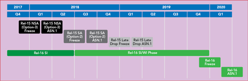
Figure 1 3GPP 5G standards timeline.
5G LANDSCAPE
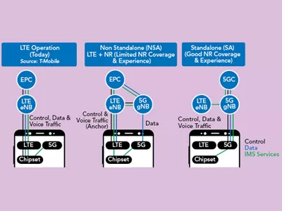
Early work on 5G specifications focused on enhanced mobile broadband (eMBB) as the first 5G use case. eMBB is expected to deliver data rates up to 20× today’s LTE speeds. The first phase of 3GPP Release 15, published in December 2017 (see Figure 1), included draft specifications for the non-standalone (NSA) 5G New Radio (NR). NSA uses an LTE anchor band for control, with a 5G NR band to deliver faster data rates (see Figure 2). This is designed to let operators deliver 5G speeds more quickly by using their existing LTE networks.
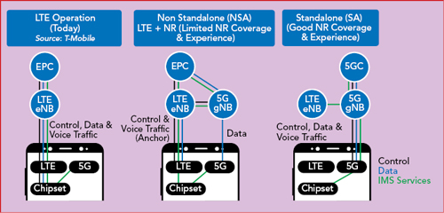
Figure 2 NSA and SA implementation options compared with LTE.
In June 2018, 3GPP followed up with specifications for the 5G standalone (SA) NR, which removes the need for an LTE anchor and requires a full 5G network buildout. As shown in Figure 1, the standards group also defined a timeline for the next 18 months, including a “late drop” of additional Release 15 features and a work schedule for Release 16, which will begin to expand 5G specifications beyond mobile broadband to a vast range of new applications, including autonomous vehicles and the IoT.
To deliver the promise of faster data speeds and support increased capacity, 5G will massively increase the spectrum range and bandwidth used for cellular communications. Spectrum is being allocated in two frequency ranges: sub-6 GHz, designated FR1, and mmWave, designated FR2 (see Figure 3). The initial mobile deployments will use FR1, which includes several new 5G bands above 3 GHz. The technical approach for supporting mmWave frequencies in handsets is being developed, but the technology is not as mature as for the sub-6 GHz bands.
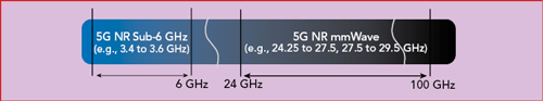
Figure 3 The 5G spectrum will comprise new bands below 6 GHz and at mmWave frequencies.
In FR1, the maximum bandwidth for a single carrier is 100 MHz, 5× LTE’s 20 MHz maximum. The 5G specifications mandate that handsets support two uplink and four downlink carriers in the bands above 1 GHz, for a total of 200 and 400 MHz, respectively. The Release 15 specifications include over 600 new carrier aggregation (CA) combinations, including many NSA permutations of 4G and 5G bands. The challenges managing this unprecedented bandwidth and CA combinations ripple through the entire RF subsystem. Adding to the complexity, 5G defines two alternative waveforms: CP-OFDM and DFT-s-OFDM. CP-OFDM offers very high spectral packing efficiency in resource blocks and good support for MIMO. DFT-s-OFDM, which is the same waveform used for the LTE uplink, provides less efficient spectral packing but greater range.
IMPACT ON HANDSET DESIGN
5G will have a huge impact on the handset RF front-end (RFFE). The standard requires handsets to squeeze additional RF complexity into essentially the same amount of space (see Figure 4). Innovative approaches are needed to support the requirements for multiple simultaneous uplink and downlink connections, and the RFFE needs to support this massive bandwidth while providing very high linearity and managing power consumption.

Figure 4 Complexity of the RF front-end in the 5G smartphone, not including any mmWave bands.
NSA Dual-Connectivity
Although 5G NSA provides operators a way to accelerate 5G deployment, it adds RF complexity because it requires dual LTE and 5G connectivity. In some cases, the handset may be transmitting on one or more LTE bands while simultaneously receiving on a 5G band. This greatly increases the possibility that harmonics of the transmit frequencies will desensitize the receiver. One example is the CA combination of LTE bands 1, 3, 7 and 20 with the new 5G FR1 band n78. n78 occupies a much higher frequency range than the LTE bands and is very wide, from 3.3 to 3.8 GHz. This increases the potential that harmonics generated by transmission on one of the LTE bands will fall into the n78 frequency range. Filtering to attenuate the harmonics can increase RFFE insertion loss, driving up the required power amplifier (PA) output power and reducing total system efficiency.
Massive Bandwidth and New Waveforms
The combination of massive bandwidth, the new CP-OFDM waveform and higher output power presents significant challenges for RF linearity and power management. In 4G handsets, envelope tracking (ET) is widely used to minimize PA power consumption. ET optimizes efficiency by continuously adjusting the PA’s supply voltage to track the RF envelope. However, when 5G is first deployed, envelope trackers are only expected to support a maximum bandwidth of 60 MHz, which is not wide enough to support 100 MHz 5G carriers. As a result, PAs must operate in fixed voltage, average power tracking (APT) mode for wideband transmission, which will reduce efficiency and battery life.
Adding to the challenge, the new CP-OFDM waveform has much higher peak-to-average power ratio (PAR). Combined with the increased channel bandwidth, this requires greater PA back-off for 5G compared to LTE, to avoid exceeding regulatory limits and maintain the linearity required for high-quality data links. Finally, many operators are planning to implement the Power Class 2 standard to maximize the handset’s operating range with 5G. Power Class 2 doubles the output power at the handset antenna to overcome the increased propagation losses of the higher frequency FR1 bands.
The combination of these three requirements—increased bandwidth, new waveform and higher output power—creates a very challenging linearity requirement for the PA design, with the potential for reduced efficiency in the transmit chain.
4 × 4 MIMO
While LTE requires two download pathways for receive diversity, 5G mandates four independent RF downlink paths for the bands above 1 GHz, to deliver higher data rates via 4× MIMO and CA. 5G also specifies two optional uplink paths in some bands. The challenge for handset manufacturers is how to fit these additional signal paths into the limited space allocated to the RFFE.
Increased integration is key to solving this problem, using integrated modules that typically combine PAs, switches and filters. In addition to saving space and increasing performance, integrated modules provide pre-tested RF building blocks that will help handset makers meet the industry’s demanding handset development cycles. Unlike the previous transition from 3G to 4G, where handsets were largely implemented using discrete components, there is near unanimous agreement among manufacturers to use integrated RFFEs to speed their first 5G devices to market.
Space for Antennas
The rise in RF complexity is also driving up the number of antennas toward the practical limit achievable in a handset. To support 4× downlink MIMO, dual uplink MIMO, the wider range of frequency bands and requirements such as 2× Wi-Fi
MIMO, the number of antennas is expected to increase from the three to five in today’s LTE handsets to four to eight—or more—in 5G smartphones. At the same time, the industry’s shift to full-screen smartphone designs is actually reducing the space available for antennas, by shrinking the bezel area that houses the cellular antennas. The need to fit more antennas into less space means antennas must be smaller and, as a result, are less efficient.
These trends will drive the adoption of two categories of antenna solutions in the RFFE. One is antenna tuning, which enables each antenna to be tuned to the operating frequency band so that it is more efficient. To some extent, antenna tuning is already used in LTE handsets, largely to increase performance. With 5G, antenna tuning will become necessary to maintain performance, given the limited number of antennas and the broader range of frequencies they must support. The other antenna technology, antenna-plexers, will expand from being a high performance option used in some LTE handsets to a must-have technology in 5G. Antenna-plexers cover multiple frequencies with a single module that allows multiple RF pathways to simultaneously connect to the antenna, while preventing interference among the pathways. Currently used in some LTE handsets for routing CA signals, antenna-plexers will be essential in 5G handsets to support the massive number of dual-connectivity CA options defined in Release 15 and future releases.
SOLVING THE CHALLENGES
Behind the hype about 5G, the reality is that deployments are approaching more quickly than originally anticipated, increasing the pressure on smartphone manufacturers to add 5G functionality. The new standards introduce unprecedented RF challenges, including new levels of complexity, massive bandwidth, linearity and power management.
As 3GPP defines the 5G standards, Qorvo and other RFFE suppliers are supporting the effort, collaborating with the wireless infrastructure manufacturers, network operators, chipset providers and smartphone manufacturers. As with the previous technology transitions, innovative new RF solutions will be required to solve the complex challenges of 5G, enabling manufacturers to release new products to consumers.