
Although there is considerable overlap in the subcomponents of ultra wideband (UWB) communications and UWB radar/sensor systems, it is natural to treat the history of the two systems separately for several reasons. Whereas a UWB communications system uses subcomponents based on principles that have been known for decades, a UWB radar/sensor system uses subcomponents based on principles novel to the radar community. UWB radar/sensing offers the capability of high resolution target imaging and detection, and has achieved some commercial success in ground, wall and foliage penetration and target imaging, while UWB communications have yet to demonstrate significant virtues. UWB radar systems are also less likely to cause interference to conventional receivers. Part I of this article will address UWB communications, to be followed by Part II, which will explore UWB radar/sensors. In both parts, the pioneering, innovative and fundamental contributions to the field are summarized, and problems in UWB interference testing and application are addressed.
The term ultra wideband or UWB signal has come to signify a number of synonymous terms such as impulse, carrier-free, baseband, time domain, nonsinusoidal, orthogonal function and large-relative-bandwidth radio/radar signals. Here, the term UWB includes all of these. (The term ultra wideband, which is somewhat of a misnomer, was not applied to these systems until about 1989, apparently by the US Department of Defense.)
Contributions to the development of a field addressing UWB RF signals commenced in the late 1960s with the pioneering contributions of Harmuth at Catholic University of America, Ross and Robbins at Sperry Rand Corp., Paul van Etten at the US Air Force's (USAF) Rome Air Development Center, and in Russia. The Harmuth books and published papers, 19691984, placed in the public domain the basic design for UWB transmitters and receivers. At approximately the same time, the Ross and Robbins (R&R) patents, 19721987, pioneered the use of UWB signals in a number of application areas, including communications and radar, and also using coding schemes. Ross' US Patent 3,728,632, dated 17th April, 1973, is a landmark patent in UWB communications. Both Harmuth and R&R applied the 50 year-old concept of matched filtering to UWB systems.
Van Etten's empirical testing of UWB radar systems resulted in the development of system design and antenna concepts (Van Etten, 1977). In 1974 Morey designed a UWB radar system for penetrating the ground, which was to become a commercial success at Geophysical Survey Systems Inc. (GSSI). Other subsurface UWB radar designs followed (for example, Moffat & Puskar, 1976). The commercial development of sample and hold receivers (mainly for oscilloscopes) at Tektronix Inc. in the late 1960s, for example, also aided the developing UWB field. For example, the Tektronix time domain receiver plug-in, model 7S12, utilized a technique which enabled UWB signal averaging -- the sampling circuit is a transmission gate followed by a short-term integrator (Tektronix, 1968). Other advances in the development of the sampling oscilloscope were made at the Hewlett Packard Co. These approaches were imported to UWB designs. Beginning in 1964, both Hewlett Packard and Tektronix produced the first time domain instruments for diagnostics.
In the 1960s both Lawrence Livermore National Laboratory (LLNL) and Los Alamos National Laboratory (LANL) performed original research on pulse transmitters, receivers and antennas. Cook and Bernfeld's book (1967) summarized developments in pulse compression, matched filtering and correlation techniques which began in 1952 at the Sperry Gyroscope Co. In the 1970s LLNL expanded its laser-based diagnostics research into pulse diagnostics. Russian developments of this time will be addressed in Part II.
Thus, by the early 1970s, the basic designs for UWB signal systems were available, and there remained no major impediment to progress in perfecting such systems. In fact, by 1975 a UWB system -- for communications or radar -- could be constructed from components purchased from Tektronix. After the 1970s, the only innovations in the UWB field could come from improvements in particular instances of subsystems, but not in the overall system concept itself, nor even in the overall subsystems' concepts. The basic components were known -- pulse train generators, pulse train modulators, switching pulse train generators, detection receivers and wideband antennas. Moreover, particular instances of the subcomponents and methodologies were also known -- avalanche transistor switches, light responsive switches, use of subcarriers in coding pulse trains, leading edge detectors, ring demodulators, monostable multivibrator detectors, integration and averaging matched filters, template signal match detectors, correlation detectors, signal integrators, synchronous detectors and antennas driven by a stepped amplitude input.
In 1978 Bennett & Ross summarized the known pulse generation methods. Since that time there have been numerous sessions at various conferences, including the Society for Photo-Optical Instrumentation Engineers (SPIE) meetings, at meetings held by LANL, by Polytechnic University in Brooklyn, NY, and at other national meetings, where the many approaches to pulse generation techniques have been, and continue to be, discussed.
From 1977 to 1989, there was a USAF program in UWB system development headed by Col. J.D. Taylor. By 1988 the present author was able to organize a UWB workshop for the US Department of Defense's DDR&E, which welcomed over 100 participants (Barrett, 1988). At this time, there was already substantial progress in UWB in the former Soviet Union/Russian Federation1 and in China2 , which paralleled the progress in the US. There were also very active academic programs (for example, at LLNL, LANL, University of Michigan, University of Rochester and Polytechnic University) which focused on the interesting physics of short pulse transmissions that differed from the physics of continuous or long pulse signals, especially with respect to interactions with matter.3
In 1994, T.E. McEwan, then at LLNL, invented the micropower impulse radar (MIR), which provided for the first time a UWB operating at ultra low power, besides being extremely compact and inexpensive (McEwan, 1994, 2000). This was the first UWB radar to operate on only microwatts of battery drain. The methods of reception of this design also permitted for the first time extremely sensitive signal detection.
The methods of data encoding in UWB communications systems were introduced decades ago. For example, Sobol provides historical perspective on microwave communications and on the data encoding technique of pulse-position modulation, which is often used in UWB communications. He wrote that in 1943 the U.S. Army approached AT&T to develop a microwave radio system: "A similar system was under development by the British, and early models were successfully used by them in the North African campaign. The first prototypes of the U.S. Army radio, the AN/TRC/6, were completed at the end of 1943, and production started shortly thereafter. The AN/
TRC-6 (Black et al., 1946) was a pulse-position modulation system that provided eight duplex voice channels through time division multiplexing and operated at 4.5 GHz." (Sobel, 1984, p. 1174)
There are even patents that antedate the UWB developments of the 1970s. In 1954 De Rosa obtained a patent for an early impulse (UWB) system, having filed for the patent in 1942. Also, Hoeppner (1961) patented a representation of a pulsed communications system. As in current UWB systems, Hoeppner's requires pulse detector timing circuitry, even if the pulses have a higher duty cycle than later-proposed UWB systems. The essential elements of an impulse radio transmission system were known even at this time.
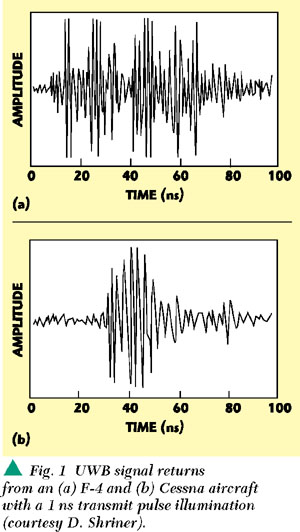
By 1975 it was possible to build a UWB system from purchased Tektronix parts, and in 1978 Bennett and Ross published the schematics for a UWB radar system, as shown in Figure 1. After the 1970s the emphasis swung to developing particular instances of the known technology, and understanding the implications of transmitting transient pulses in a world dependent on non-interfering RF communications and sensing. Although UWB systems employ a homodyne receiver approach (cf. Barrett, 1995b) -- as opposed to a heterodyne approach (superheterodyne receiver) -- UWB systems remain confined by, and do not escape from, the usual engineering trade-offs of time, bandwidth, signal-to-noise ratio and electronic complexity.
The UWB approach to communications is -- if not a shift in paradigm -- at least a shift in emphasis with respect to use of the available time-bandwidth-power product. Figure 2 shows one aspect of this shift for communications applications. The fundamental emission according to the FCC (2000, p. 3) is the main lobe when viewed on a spectrum analyzer and the sidelobes are not considered, or 2/τ, where τ is the pulse temporal length. It can be the resonant frequency of the transmitting antenna used which determines the center frequency of the radiated pulse (FCC, 2000, p. 2). In Figure 2a, the box depicts the product of (individual pulse or symbol) bandwidth, (one method defining this bandwidth is B = 6.36/τ, where B is the bandwidth in MHz, τ is the emitted pulse duration in microseconds at the 50 percent amplitude (voltage) points (Annex J of Chapter 5 of the National Telecommunications and Information Administration's Manual of Regulations and Procedures for Federal Frequency Management, quoted by the FCC (2000, p. 2, footnote 8)), duration and peak power (expressed as S/N. S/N = signal power/noise power, where power is defined in units of J/s or VI or kg.m2 /s2 .m). It should be noted that the power spectrum or the power density spectrum, both of which are based on harmonic analysis, do not easily apply to single transient events unless careful attention is paid to the sampling rate. It should be understood that a very short duration pulse of low energy creates fields of high electric field strength (V/m) and power (V*I). With energy (J) constant, still greater field strengths and powers can be created by further shortening of the temporal length of the pulse. The FCC has correctly questioned reliance on the power spectral density as the appropriate measure for UWB emissions (cf. FCC (2000, p. 15, paragraph 34)), yet paradoxically has proposed (ibid, p. 18, paragraph 15) that for UWB emissions > 2 GHz, limits still be based on power spectral density measurements (signal energy level per unit bandwidth). As the signal duration decreases, the bandwidth increases and the S/N per frequency (S/N/ω = J/s*ω or VIs*ω or kg*m2 /s2 * ms*ω.) decreases. Moreover, the S/N per frequency decreases below the threshold of frequency selective receivers, which is a major argument made by UWB proponents that UWB systems are able to operate in the presence of frequency selective receivers without interference. The methods used to reliably receive a UWB signal with such low S/N per frequency are shown in Figure 2b. They include a high sampling rate receiver to capture in a nonsynchronous (homodyne) fashion all the signal energy in a minimum number of sampling bins, summing across all the contemporaneous signal bandwidth, which implies a receiver front-end open to that instantaneous ultra widebandwidth and thus also open to noise, or signal averaging or matched filtering (which lowers the data rate), or counteracting the low power per frequency by increasing to high signal transmit power, which implies interference to other receivers, synchronous or otherwise. In other words, engineering trade-offs still apply. Each advantage offered by UWB is offset by a disadvantage, the cure for which is another disadvantage. The engineering goal remains -- as always -- balanced optimization.

Essentially, a UWB communications system trades pulse shortness (gaining a high signal/symbol rate) in exchange for two other variables: bandwidth (which becomes wider) and S/N (which is reduced). Greater bandwidth use requires FCC approval and a lower S/N requires signal averaging, which then lowers the signal/symbol rate and thus the channel capacity (data rate). Lowering the signal/symbol rate, plus the fact that the symbol/signal of a UWB system has an informational value no higher than 1 bit (and after signal averaging much less), defeats the aim, if that aim is to achieve high capacity or high data rate. Of course, these trade-offs can, to some extent, be alleviated by transmitting pulses, the lowest frequency components of which are higher than FCC Part 15 bands (above ~6 GHz), or by using higher power (if permitted and non-interfering). However, both of these strategies are also available to conventional and noninterfering wireless communications systems.
There is no escape from these trade-offs. As in the case of more conventional communications systems, the UWB wireless system designer must balance trade-offs among high bandwidth efficiency, low transmission peak power, low complexity, flexibility in supporting multiple rates and reliable performance as expressed in bit error rates.
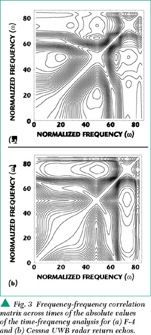
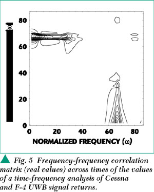
But even the representation of the time-bandwidth-S/N product is incomplete in assuming that the power spectrum of a UWB pulse or trains of pulses is flat. Only harmonic signals can be transmitted; mathematical distribution functions such as a Dirac delta function are not physical and not transmittable. A form of the ambiguity function or matched filtered response to a UWB pulse train on which has been imposed an interpulse-interval temporal code -- that is, the train has been dithered -- is shown in Figure 3. There is always a central peak in the energy/power spectrum corresponding to the energy/(sampling time) of the individual UWB pulse, regardless of the extent of dithering. There have been claims that pulse dithering will reduce the power in a UWB pulse aperiodic train to a flat spectrum, but such a misleading prediction is due to inadequate (nonNyquist) sampling of the individual pulse within the pulse train, or because the sampling is intentionally set to the pulse repetition rate (PRF). Thus, the time-bandwidth-S/N product incompletely represents the spread of energy captured by a matched filter capable of sampling at the Nyquist rate. State-of-the-art spectrum analyzers do not sample fast enough to capture the peak power of the individual UWB pulse, and thus misrepresent the energy and power in a UWB pulse train. A fast (> 20 GHz) sample-and-hold oscilloscope will capture the peak power in the individual UWB pulse, but is also not suitable for capturing the peak power of singular peak power events in aggregated pulses from different emitters. Thus, apart from the electronic upset capability due to the power of the PRF and the peak power of the individual UWB signal, there are also the sporadic combinations of peak powers due to the individual peak powers in aggregated networks of UWB emitters. Detecting the latter is a technical challenge now met by real-time digital phosphor oscilloscopes (for example, the Tektronix 7000 series). Only such real-time oscilloscopes are capable of capturing UWB aperiodic transient noise.
The ambiguity function representation of a dithered UWB train of signals provides an idealization of a test instrument matched, not to the PRF, but to the individual UWB signal. Any cut in one direction gives the power density spectrum at multiples of the set frequency. Any cut in the other direction provides the autocorrelation at multiples of a set sampling time. Increasing the amount of dithering (mismatching to the test instrument as a matched filter) can result in narrowing the central peak (to a limit), but the central peak (or spike) will remain of the same height, no matter the amount of dithering.
However, it is easy to see how false claims can be made concerning the effect of dithering. If the sampling time is inadequate (too long) -- as it will be with state-of-the-art spectral analyzers -- then the central peak will not be captured. This inadequacy in the sampling rate of test equipment gives rise to the spurious claims that dithering (applying an inter-pulse interval code to) a train of UWB signals results in a flat power density spectrum.
The analysis method of choice for individual UWB signals is a generalization of the Fourier transform, which captures not only signal harmonic components, but also signal damping -- the Laplace transform. The Laplace transform of an example UWB signal is shown in Figure 4. This representation of a UWB signal indicates the transient nature of the signal and does not confuse a physically transmittable pulse with a mathematical distribution function. A more comprehensive analysis of UWB communications would involve the following: measuring the peak, as well as the average, power in the time domain, and with spectrum analyzers used only as ancillary equipment; describing UWB individual pulsed emissions in Laplace analysis form -- an analysis form which is more general than Fourier analysis and addresses the rise and fall times (damping) of the UWB signal; and describing the UWB individual and aggregated emissions in ambiguity function form.

The ambiguity function describes how the energy in a signal can be redistributed in the time-frequency plane by pulse train interpulse-interval temporal codes (dithering), and demonstrates two important points. First, if the pulse/pulse train energy is imagined as sand on the frequency-time plain, then no sand (energy) can be removed from the plain. That is, the sand (energy) can be piled up differently, and distributed differently, but none can be removed from the frequency-time plain/plane. Second, no matter how much the sand (energy) is redistributed and becomes flattened on the frequency-time plain/plane, the central peak -- that which is due to the peak power of the individual UWB pulse -- always remains the same height. That peak power cannot be diminished.
There have been claims by UWB proponents that a UWB signal will remain under the noise floor of a conventional receiver and thus provide no influence on that receiver's performance. The first point denies the validity of that statement. Referring to the aforementioned analogy, and assuming the sand deposited on the frequency-time plain/plane description of a victim receiver is new sand (new energy), it will therefore lower the ratio of the central peak of the frequency-time description of that receiver, with respect to the level of energy elsewhere. Another way of saying this is that the signal-to-noise ratio in the receiver will be lowered, because the noise floor will be raised. And, if many UWB transmitters are involved in aggregated networks, the noise floor of the victim receiver will be raised more. Hence, there is no escape from normal engineering trade-offs.
The second point argues for the use of time domain testing of UWB signals, with (> 20 GHz) sample-and-hold oscilloscopes for periodic signals, real-time digital sampling oscilloscopes for one-shot signals, and digital phosphor oscilloscopes for one-shot aperiodic signals monitored over time. Laboratory testing of UWB systems for interference is obviously only as accurate as the laboratory equipment used. Therefore the laboratory testing should be supported by simulation.
It might be supposed that comparisons between UWB communications and conventional communications could proceed using the conventional definitions for the variables in the conventional range equation. In most cases, these variables do have the same connotation, but in the case of UWB receiver noise, they do not. If the claim is valid that a UWB signal is below the threshold of conventional heterodyne receivers, it must also be valid that conventional transmitters are transmitting narrower band signals, which in many cases are above the threshold of UWB receivers. Therefore a UWB receiver, which must be ultra broadband in its front-end, is more vulnerable to interference noise than conventional receivers of narrower bandwidth. Now it is generally considered that the fundamental receiver noise mechanism is thermal noise and the noise variance is related to the effective noise bandwidth of the receiver. That bandwidth is approximately one half the signal bandwidth. It is also generally assumed that the most common communications channel is one with additive white Gaussian noise (AWGN). In the case of AWGN, the noise arises from the receiver itself, that is, from thermal noise in the first amplifier stage. However, in the case of UWB, this may not be the only noise present in the communications channel. Even if it is the only noise present, it is conventionally assumed that an observation of this noise through an unbounded bandwidth will have unbounded power. (That assumption is unrealistic, but always assumed in the AWGN case.) If this assumption is adopted in the case of a UWB ultra broadband receiver, which is also a homodyne receiver, then if Eb is the signal energy per bit for, a spread spectrum direct sequencing system (DSSS), for example, and also a UWB system, N0 is the channel noise for DSSS, and n0 is the channel noise for UWB. So, taking the above remarks into consideration
The ultra wideband receiver front-end and the interference from conventional communications transmitters would preclude equivalencies. Therefore, direct performance comparisons assuming an equivalencie become problematic.
In comparing a UWB system with a DSSS system, it might be assumed that there is an exact comparison between the UWB bandwidth produced by the shortness of the pulse duration and the DSSS bandwidth produced by spreading from a chipping sequence. However, this comparison is misleading. In the case of UWB, all the energy across the bandwidth constitutes the signal. In the case of DSSS, however, only that energy within the spread bandwidth present before spreading and before transmission constitutes the signal, with the remainder of the energy in the spread bandwidth after reception being rejected as noise. The difference between the two approaches is indicated by the fact that shortening a UWB pulse must be compensated by an increase in the peak power to preserve the energy per bit, but the energy per bit is independent of the chip rate and dependent on the data rate in the case of DSSS.
It might also be supposed that a UWB communications system has an advantage over a DSSS system in that UWB can utilize coherent addition of N pulses to achieve a bit signal-to-noise, which is N times the S/N of an equivalent DSSS system. However, the DSSS equivalent of UWB coherent addition is processing gain, not bit S/N. Furthermore, just as a DSSS system trades the bandwidth available for data transfer, and thus data rate as well, for processing gain and S/N, so UWB trades data rate for coherent addition and S/N. Rather than supplying an advantage, UWB coherent addition is merely a strategy for maximizing S/N in the presence of noise in the channel, just as processing gain is such a strategy for DSSS to maximize S/N. In both instances, if all else remains constant, the increase in S/N is achieved at a price -- a decrease in data rate. If the data rate remains constant, then there are other penalties for the adoption of these strategies. Just as there is minimal processing gain for a high data rate DSSS system, so there is minimal coherent addition for a high data rate UWB system. Both approaches must then increase the average power, and, in the case of a UWB system, the peak and average power will eventually equalize. A possible choice for a UWB system is to increase the pulse repetition rate to maintain a set data rate, but just as in the case of a DSSS system in which the chip rate is increased, the penalty for this choice is an increase in system complexity, as well as average power. Thus, there is a direct correspondence between the number of pulses per data bit in a UWB system using coherent addition and the number of chips per data bit in a DSSS system. Of course, if the data rate is of no consequence, then the choice of system and compensating penalties will be dictated by other considerations. It is also worth mentioning that these penalties are a consequence of figures of merit which address peak power. Confusion arises when comparisons are switched between peak and average powers of different communications systems, and the corresponding figures-of-merit changed at will.
MAJOR COMPONENTS OF A UWB RADIO COMMUNICATIONS SYSTEM
The major components of an impulse radio system are methods for generating pulse trains (transmitter sources), methods for modulating a pulse train, methods for switching to generate RF pulse train signals, methods for pulse detection and receiving, and appropriately efficient antennas. The essential five major components were presented in the Ross US Patent 3,728,632 of April 17, 1973 (Ross, 1973a) and the Harmuth books and papers (19691990), and since that time numerous variations on the means of implementation have been proposed.
Methods for Generating Pulse Trains (Transmitter Sources)
In the 1970s, Harmuth discussed a variety of impulse radiators (1977b, pp. 235399; 1972, pp. 244291) and presented approaches to practical radiators. Examples of radiators and selective receivers were discussed at this time.
Methods for Modulating a Pulse Train
A variety of methods for modulating a pulse train have been known for decades, even before the age of transistors. Harmuth (1969, 1972; Smith, 1966, p. 438) addressed some early methods.
Methods for Switching (RF Pulse Generation)
Some of the many methods available for transmitter sources are light-activated semiconductor switches (LASS) - these switches are generally Si-based (cf. Auston, 1975; Mourou & Knox, 1979; Nunnally & Edwards, 1991; Loubriel et al., 1993; Kingsley et al., 1995); light-activated bulk avalanche semiconductor switches (BASS) - these switches are generally GaAs-based (cf. Jayarman, S. & Lee, C.H., 1972; Vainshtein et al., 1988; Pocha et al., 1991; Loubriel et al., 1993; Sarkar et al. 1993; Loubriel et al., 1995; Kingsley et al., 1995); thyristors based on GaAs (cf. Platts et al., 1995); semiconductor-based pulse compressor systems (cf. Edwards et al., 1995); Marx bank pulse generators (cf. Platts, 1991; Platts et al., 1995; Edwards et al., 1995); and avalanche drift diode generators (cf. Grekov et al., 1981; Grekhov et al., 1985; Edwards et al., 1995). In addition, there are vacuum triodes (cf. Platts et al., 1995); magnetic switches (cf. Platts et al., 1995); low voltage tunnel diodes (cf. Ross, 1973a, b; Ross & Lamensdorf, 1972; Ross & Robbins, 1973); high voltage avalanche semiconductor diodes; laser diodes; resonant microwave compressors (Didenko & Novikov, 1991; Yushkov & Badulin, 1997); and avalanche transistor/diode methods of switching. A simple method of generating UWB signals is to use avalanche transistors and has been known for many years. Morey (1974) cited a transistor in the avalanche mode as a suitable means for a pulse generator in a UWB system. Table 1 from Ross (1986) lists the avalanche transistor as one method (among others) for achieving pulse sources. Andrews (1986) reviewed the field of fast pulse generators and, in particular, Picosecond Pulse Labs avalanche transistor pulse generators (p. 103). Astanin & Kostylev (1989), addressing usage not only in the former Soviet Union, states: "Generators based on avalanche transistors are widely used." (p. 108)

One final switch method involves light activated switch methods for switching generators -- RF short-pulse generators using laser-induced photoconductivity in high resistivity semiconductors were demonstrated by Auston (1975) in silicon. Linear photoconductive semiconductive switching has been an active field since that time (cf. Lee, 1984; Rosen & Zutavern, 1994). A variety of semiconductors have been employed in photoconductive switches, for example, Si, GaAs, ZnSe, diamond and SiC (cf. Kingsley et al., 1995). The activity in the field of light activated switching has increased to such an extent that almost yearly meetings are held by the SPIE. The patent by Kim et al. (1993) also addresses light activated switching for impulse systems.
Methods for Pulse Detection and Receiving
Methods for pulse detection and receiving include leading edge detection, sampling bridge circuit methods, monostable multivibrator methods, integration and averaging methods, template signal match detection methods, correlation detection methods, signal integrating methods and synchronous detection methods. All such methods have been known since the 1960s and 70s (cf. Malmstadt & Enke (1963) for a review of early examples of these methods). A nonexhaustive list of these well-known methods includes leading edge detection, which has long been in use (cf. Meleshko, 1987, p.58), and sampling bridge circuit methods, commonplace by 1968. The Tektronix Instruction Manual for the Type S-2 Sampling Head (1968) provides a sampling bridge circuit. Also included are monostable multivibrator means, a technique which has been widely used for over fifty years (cf. Malmstadt & Enke, 1963, p. 440), integrating and averaging methods -- electronic integration and averaging is a technique commonly used over the last fifty years (cf. Smith, 1966, p. 450) -- and the commonplace template signal matched detection (for example, Meleshko, 1987, Fig. 32, p. 65). A template match is essentially a logical and operation or a cross-correlation satisfying the long-known Wiener-Hopf equation. It should be noted that template pulse mixing a signal with a gating pulse is not the same as summing a signal with a strobe pulse, and is also a much less sensitive detection operation.
Correlation detection of RF signals is now universal (cf. Lee, 1960; Skolnik, 1962, p. 275). The sliding correlator as applied to impulse communications and radar was reported in the open literature long ago (cf. p. 143, and Chapter 6 Advanced Signal Design and Processing of Skolnik, 1962). Other examples of early sliding correlators are shown in Harmuth (1981, 1984), as shown in Figure 5.
Signal integration methods to match a preset criterion (for example, summed amplitude) are commonplace. For example, the 1968 Tektronix sampling circuit is a transmission gate followed by a short-term integrator (Tektronix, 1968). Synchronous detection methods are widely used and a long-known procedure. According to Fink and Christiansen: "Figure 14-86c shows a product (synchronous) detector. This type of detector has been used since the advent of single-sideband transmission." (1975, p. 14-69)
In addressing monocycle signals from antennas driven by stepped in amplitude (ramp function) driver methods, Cronson (1975) showed that virtually any frequency-coded pulse could be generated by a step function (cf. Ross, 1986, p. 11). This method has also been studied for a long period of time (see Harmuth, 1981, p. 4854, 77; 1990, Preface and section 1.7 - A Guide to Reading, p. 52).
Use of subcarriers in pulse trains, that is, subcarrier modulation, is a well-known modulation method and is explained in many textbooks. Transferring the method to the time domain introduces no new principles. The use of subcarriers and subband coding is a well established field in electrical engineering. Later attempts to patent the well-known modulations of frequency modulation (FM), amplitude modulation (AM), phase modulation, frequency shift keying (FSK), phase shift keying (PSK), pulse FM and Manchester coding, if taken seriously, would undermine the field of radio communications inasmuch as these methods are the backbone of this mature field.
Appropriately Efficient Antennas
The antennas used in UWB communications, or being considered for use, include loaded dipoles, TEM horns, biconicals, ridged horns, spiral and the large current antenna. All have a variety of merits and demerits.
DETECTION & AMPLIFICATION
There are a number of approaches to the detection and amplification of trains of UWB signals. In most cases, there is an allocation of one-to-many in the assignment of bits to pulses to be transmitted. After 1945 the use of the correlation detection receiver became commonplace. Skolnik (1962), in his introductory book and shown in Figure 6, described the use of correlation methods in the detection of weak signals and cited the following earlier references: Lee, 1950; Lee & Wiesner, 1950; Lee Cheatham & Wiesner, 1950; Singleton, 1950; Fano, 1951; Rudnick, 1953; George, 1954; Green, 1957; Horton, 1959; and Raemer & Reich, 1959. A synchronous detector is also displayed in Fink & Christiansen (1975), and shown in Figure 7. There are a variety of ways to trigger the receiver -- on the pulse rise-time, level-detection or integration over time.


In the case of the correlation receiver detector, UWB and gate pulses are multiplied to produce a short output unamplified pulse whenever there is a coincidence. Next, the resultant is fed to a (short-term) integrator or averager to produce a reduced amplitude stretched signal output. If the integrator time is sufficiently long (conventional correlator), or a second long-term integrator is employed, the output will then represent the average of the many high repetition rate pulses fed to the correlator. Unfortunately, the integrator not only acts as a detector, but also reduces the input amplitude in the step from narrow-pulse, low duty cycle to averaged output. The long-term integrating correlator thus effects a many-to-one detection of averaged inputs prior to any amplification.
The micropower impulse radar (MIR), or "radar on a chip," offered an alternative to correlation detection (McEwan, 1994, 2000). The MIR, shown in Figure 8, is an integrating peak detector (McEwan, 1994), as opposed to the multiply-and-average correlation receiver detector previously described. In the case of the MIR receiver detector, UWB and gate pulses are summed algebraically to form the input to a peak detector, that is, the low amplitude UWB pulse and the high amplitude gate pulse, which when summed, are above threshold for peak detection, but individually, are not. Moreover, it is not a single UWB pulse which, together with the gate pulse, provides the peak detected signal, but the (long-term) summing of a series of UWB inputs. Thus, the detector is triggered by the simultaneous occurrence of a summed series of low amplitude UWB signals and a coincident large amplitude gate pulse which, together, are algebraically summed. The coincident summing method of a large gate input and summed low amplitude signals effects a many-to-one, peak signal detection process.

THE TEKTRONIX SYSTEM (1975)
In 1968 Tektronix offered for sale a sampling head consisting of a strobe generator, a sampling bridge shown in Figure 9, a blow-by and trigger pickoff and a preamplifier. By 1975 it was possible to build either a UWB communications system or UWB radar using Tektronix laboratory test equipment. Figure 10 shows such a system using a Tektronix 7S12, an S-4 sampler for receiving means, and an AM502 differential amplifier with filters as a signal processing means.
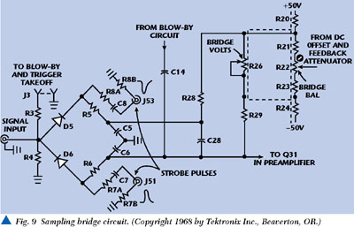

It is instructive to examine the means of achieving detection. The sampling bridge circuit does not amplify, but merely provides an error signal. The Tektronix manual states: "During the sampling time, the strobe pulses forward bias D5 and D6. By normal bridge function, the conduction of D5 and D6 charges or discharges C5, C6, C7 and C8. The voltage charge on these capacitors changes about 2 1/2 percent of the difference between the feedback and DC offset voltage and the incoming signal voltage. This voltage change, called the error signal, is amplified in the preamplifier." Thus, diodes D5 and D6 form a sampling bridge or transmission gate driven by strobe pulses at J51 and J53. Resistors R5 and R6 = 200 Ω and capacitors C5 and V6 = 5 pF for a short-term integrator (balanced configuration) with a 1 ns time constant. D5 and D6 conduct for approximately 40 to 50 ps, so that integrators charge to about 2-1/2 percent of the signal input voltage during the time that the D5 and D6 conduct, providing a voltage transfer efficiency of 2-1/2 percent. Therefore this approach, although much used and imitated, is nonetheless an inefficient detector.
HARMUTH SYSTEMS
Beginning with publication of the first edition of Transmission of Information by Orthogonal Functions in 1969, Harmuth has addressed UWB in all its manifestations, but under the synonyms impulse, carrier-free, time domain, nonsinusoidal, orthogonal function, Walsh functions and large-relative-bandwidth radio/radar signals, not under the 1989-coined term UWB. The five basic subcomponents were also addressed in early representational form and with the electronics available at that time. The second edition of the same book (Harmuth, 1972) contains a chapter called "Nonsinusoidal Electromagnetic Waves" (Ch. 6, pp. 244291), which discusses a variety of impulse radiators, as well as the selective reception of impulse signals in mobile communications (cf. Section 5.4 Signal Selection and Synchronization, pp. 282291, with a correlation receiver shown in Figure 189 on page 289 (Fig. 5.0.1)).
Harmuth (1972) described transmitters and selective receivers for periodic waves with arbitrary time variation within the period. Harmuth (1977a) reported a more advanced form of the receiver and discussed "pulse compression" -- actually signal averaging. Harmuth (1977b) contains Chapter 3, "Electromagnetic Waves With General Time Variation," with the sections Practical Radiators, Practical Receivers and Applications to Radar. Photographs of a radiator and a selective receiver are shown, and oscilloscope recordings of nonsinusoidal waves -- specifically their electric field strengths -- are also displayed. A correlation receiver for selective reception is shown in Harmuth (1975, Fig 9).
Harmuth's Nonsinusoidal Waves for Radar and Radio Communication (1981) contains Chapter 4, "Selective Receivers," and Section 4.6, Receiver for Nonperiodic Waves. The circuit shown in that book is a correlation circuit. The correlation receiver or pulse compressor was recognized by then to be the generalized equivalent for waves with arbitrary time variation of the tuned resonant circuit for the selective reception of sinusoidal waves. The pulse compression circuits in this reference are also published in Harmuth (1979 & 1980).
Harmuth (1984) contains Section 1.2, Transmitter and Receiver for Nonsinusoidal Waves, Section 1.3, Nonsinusoidal Spread Spectrum Radio Transmission and Section 1.4, Pulse Agility Versus Frequency Agility. All of these address the major components of a UWB system.
Thus, by the early 1970s, the generic system and all of the generic subcomponents for UWB systems of whatever form were in the public domain, and by the early 1980s had been extensively discussed.
ROSS & ROBBINS SYSTEMS
Robbins (1972), Robbins & Robbins (1974), Ross & Robbins (1973), Ross (1973a, b), Ross & Robbins (1987) and Ross & Mara (1994) are patents all addressing specific embodiments of a UWB radio receiver.
The patent by Ross (1973) disclosed an impulse radio encoding intelligence on a train of pulses by pulse interval modulation or pulse position modulation (Ross, 1973, paragraph 9). This patent recognized the utility in communications systems of a wide instantaneous bandwidth (as opposed to sequential bandwidth). Subsystems of a UWB radio were disclosed by Robbins (1972), Ross & Lamensdorf (1972), Robbins & Robbins (1974) and Ross & Robbins (1987). Figure 11 shows the patented circuit diagram.

These early patents recognized that the pulse train could be modulated by a code scheme and that this method was known even prior to the patents themselves. For example, Ross states: "It will be understood by those skilled in the art that a variety of ways is available in the prior art for impressing intelligence on the carrier-less baseband pulses of transmitter 2, and for abstracting that intelligence at receiver 3 by well established demodulation techniques operating on the relatively long pulses generated in receiver 3." (1973, paragraph 13)
In 1978, Bennett & Ross published Time-Domain Electromagnetics and Its Applications. These authors wrote at a time when the term "baseband" was preferred to "UWB" or "time domain," but all these terms are synonymous. The essential five major components of a UWB system had been already presented in Ross (1973) using methods of implementation long in use as the following quotation shows: "The baseband pulse receiver 3, as has been seen, may be employed in the novel communication system to receive intelligence communications in a variety of ways, such as... Equivalent electronic operation may be readily visualized... More sophisticated arrangements for conveying intelligence messages from transmitter 2 to receiver 3 are readily apparent to those skilled in the art." (Ross, 1973, paragraph 13, line 20)
In addition: "Similarly, pulse interval modulation in transmitter 2 and cooperative demodulation in receiver 3 may be employed for conveying intelligence messages. It will be understood by those skilled in the art that a variety of ways is available in the prior art for impressing intelligence on the carrier-less base band pulses... and for abstracting that intelligence... by well established demodulation techniques..." (Ross, 1973, paragraph 13, line 55)
The claims of the Ross (1973) patent refer to particular instances of the five basic components.
THE TECHNICAL DIFFICULTIES ASSOCIATED WITH TESTING FOR UWB EMISSIONS INTERFERENCE
The testing of the effects of UWB emissions on conventional receivers is extremely complicated and difficult. This is because there are many different kinds of UWB single pulses which can range from 0.5 to 10 ns, for example, and possess different rise times or onset times, damping or fall times, and harmonic modulated components or ringing, all according to the individual drivers and antennas. There is no generic UWB individual signal or pulse. All are damped transients.
There are many different kinds of pulse repetition frequencies (PRF) possible for the many different individual UWB signals. There is no generic UWB PRF.
There are many different interpulse-interval temporal codes possible that can be imposed on the many different PRFs possible for the many different individual UWB signals. There is no generic code.
Measuring the peak power of the individual UWB pulses cannot be accomplished in real-time, but the individual pulse case can be measured with a high (for example, 20 GHz) frequency sample-and-hold oscilloscope. (A state-of-the-art spectrum analyzer can only provide a distorted average of the true power.) It is not true, as has been claimed, that a UWB transmitter emits at the power level of a hair dryer. This is a dubious statement if average power is intended; it is a false statement if peak power is intended or if the aggregated average power of disparate UWB emitters is intended.
In a network, many UWB transmitters will operate simultaneously and autonomously, constituting aggregate aperiodic interference. A sample-and-hold oscilloscope can provide a measurement of a single pulse applied repetitively, but as an aggregate of UWB emitters is continuously changing (aperiodic), this approach is not applicable -- even if a large enough aggregate of asynchronously operating transmitters could be assembled. A sample-and-hold oscilloscope samples high frequency signals utilizing a low analog-to-digital (A-D) sampling rate and using "random interleaved sampling" of a periodically repeated signal. That is, by periodically repeating a signal, such oscilloscopes permit high effective sampling rates with a lower actual sampling rate. The emissions of an aggregate of disparate pulses at disparate PRFs with disparate superimposed temporal codes constitute a noise of aperiodic transients. These aggregate emissions are discontinuous, aperiodic and nonrepeating, so a sample-and-hold oscilloscope is not the appropriate test equipment. A real-time oscilloscope is the appropriate test equipment, including the Tektronix TDS 7000 series Digital Phosphor Oscilloscopes (DPO), for example, sampling at over 20 GSps, and which store and analyzing complex signals in real-time, using three dimensions of signal information -- amplitude, time and distribution of amplitude over time; and the Tektronix TDS 694C Digital Storage Oscilloscope (DSO), providing accurate delta time measurements ±15 ps and a sampling rate of 10 GSps.
Such a noise of aperiodic transients may or may not be approximated by white noise -- more likely band-limited noise. But if an aggregate of UWB emissions were to be approximated by white noise, then each possible victim receiver would need to be tested individually for electronic upset potential. The individual testing of victim receivers is necessitated by the well-known nonlinear properties of receiver front-ends, and each receiver-type could be nonlinear in its own way.
Even here, there are technical difficulties associated with a noise-of-aperiodic-transients (perhaps approximated by white noise) analysis of victim receivers, due to the requirements that the noise be first recorded in real-time while it is applied to the victim receiver, and then that recording must be correlated with the receiver's immediately following response. The aforementioned Tektronix DPOs can provide real-time recording over substantial time, provided that sufficient memory is made available.
Confronted with the technical difficulties associated with the experimental testing for periodic and aperiodic aggregate UWB emitter interference, there would appear to be a strong argument for simulation, rather than experimental testing, of such aggregate interference over the time-frequency plane.
Note also that the FCC requires power limitations and restrictions on power at designated band edges. Moreover, the present FCC Part 15 rules do not permit damped wave emissions or the ringing of antennas, that is, spark gap transmissions. In other words, the FCC Part 15 rules require a signal carrier or average frequency for very good reasons: Before 1927, when the precursor to the FCC was formed, such emissions were a major source of interference.
In fact, the Part 15 regulations are intended for continuous waves and specifically prohibit "damped wave emissions." UWB signals are, in effect, "damped wave emissions." Therefore, if the FCC should ever consider regulating UWB signals under Part 15 rules, the FCC would need to strike the prohibition against damped wave emissions and provide separate regulations addressing peak as well as average power. If the FCC did not strike the prohibition, it might be accused of playing fast and loose with its own regulations and run the risk of being accused of dereliction of duty.
SUMMARY OBSERVATIONS
In summary, the pioneering work of Harmuth, Ross, Robbins, van Etten and Morey, as well as the extensive work in the former Soviet Union/Russian Federation, defined UWB systems, both radar and communications, and did so in a very practical manner using the electronics of the time. Others have contributed to particular instances of the subsystems described by these pioneers, but after the pioneering contributions, no one can, or should, claim to have invented the field of UWB radio, radar or communications, or to have invented a particular component or components, which made it practical. There never was a time that a particular subcomponent invention was required for UWB systems to become possible, except, perhaps, the sample-and-hold oscilloscope in past times, and the real-time digital phosphor oscilloscope in recent times. In the commercial arena, UWB radars/sensors systems have been utilized since the 1970s.
A number of summary observations can be made concerning the historical development of UWB. There is nothing new about the fundamental design of subsystems of a UWB communications system or any component part. Subsystem concepts of certain levels of sophistication or efficiency were readily available to G. Ross when he obtained his 1973 patent for a UWB communications system.
What is new is the assumption in the case of UWB communications systems that such systems can coexist without interference with other communications systems which use synchronous receivers, and are regulated by conventional FCC spectrum habitation requirements. This assumption specifically requires that the receivers of conventional systems not only normally operate at higher average power/frequency thresholds than do those of UWB receivers (which must achieve acceptable signal-to-noise levels over time either by signal averaging, or by high instantaneous signal power levels), but are also not normally subject to electronic upset by high peak power, transient UWB signals. These are two separate requirements, which are usually assumed identical.
This assumed absence of interference of UWB communications systems with other conventional receivers, and also of the electronic upset of a variety of forms of electronic equipment (for example, GPS, which operates in the 11641215, 12151240 and 15591610 MHz frequency bands), has yet to be adequately validated (cf. Aiello et al. (2000) and FCC (2000)) and there is a second assumption that pulse signals above 2 GHz are relatively noninterfering due to propagation losses (FCC, 2000, p. 13, paragraph 27). Indeed, the effect of transient RF signals, as opposed to steady state signals on materials and circuits, is a complex subject, but poorly understood (cf. Barrett, 1991; 1995a). Moreover, the effect of a train of aperiodic transient signals on conventional receivers and forms of electronic equipment may be a nonlinear temporal summation of the individual transients and a function of the relaxation time of a particular material or a particular circuit. Making the problem of interference even more complex is the fact that, although there is a short list of electronic materials, there is a long list of possible electronic circuits in victim receivers, each with a specific relaxation time regarding possible variables affecting susceptibility to interference. According to the FCC: "Typical front-end bandwidths before the first mixer in receivers; typical dynamic range limits of receiver mixers; typical IF bandwidths; and required signal-to-interference ratios for reliable performance of the system assuming interference is white gaussian noise..." (FCC, 2000, p. 14, paragraph 33) These variables are, indeed, important. However, what is meant by "typical" is usually typical peformance with respect to continuous, rather than transient, signals. Furthermore, a pulse transient is a broad spectral bandwidth signal (mathematically), but the frequencies are precisely phase-locked, not randomly phase-related as in white noise. Therefore, it is not clear that these "typical" measurements will provide an accurate prediction of interference by real transient signals. Despite this lack of knowledge concerning interference susceptibility, some UWB proponents do not believe in cumulative interference (cf. FCC, 2000, p. 21, paragraph 46).
In the case of more than one UWB communications system operating in asynchronous mode, the assumed absence of UWB-induced interference to other locally operating UWB systems has also yet to be validated. This form of interference, which may be absent or rare in the case of UWB radar, may yet be anticipated to be commonplace in the case of more widely used UWB communication systems.
Shannon's channel capacity laws are universally valid and apply to UWB communications systems, regardless of whether a government limits the bandwidth and the power used. However, UWB communications systems have yet to be evaluated with respect to both bandwidth efficiency and power efficiency. UWB communications systems' bandwidth efficiency rating -- the measure of bandwidth (that is, real bandwidth, not merely that bandwidth which can be detected above conventional receiver thresholds) used together with data rate achieved in efficiency ratings -- is presently extremely poor. UWB systems' power efficiency rating -- distance achieved for power (peak not average) used -- is also poor. (A declared motivation of the FCC interest in considering permitting the operation of UWB systems is that it "would permit scarce spectrum resources to be used more efficiently." (FCC, 2000, p. 1) However, the aim to achieve efficiency addresses the issue of whether UWB transmissions do or do not interfere with the reception of conventional frequency receivers, that is, of whether the noise floor of such receivers can be utilized without penalty. This is a different efficiency aim than the aim to achieve the highest data throughput through a channel of precisely defined and restricted bandwidth. Perhaps it is not even an aim in efficiency. Engineering trades of time, bandwidth and power assume a zero-sum game. Some proponents of UWB technology tacitly acknowledge the zero-sum game, but claim that the S/N penalties from "reuse" of spectral areas already occupied by conventional narrow and broadband systems are spread over many victim receivers. Therefore, the argument goes, the penalty per victim receiver is small. Thus, rather than using the "scarce spectrum resources... more efficiently," operation of UWB communication systems would be an exercise in interference tolerance because there must be interference regardless of how little. But tolerance is not efficiency. And the amount to be tolerated is not trivial.
A UWB communications system is a strategy -- a limiting case strategy -- of utilizing a communications channel's time-bandwidth-power product, bypassing the FCC bandwidth restrictions and allocating extremely broad instantaneous bandwidth to the symbol/signal. There are, of course, other strategies and other approaches to utilizing that same product, but keeping within FCC guidelines. In the case of UWB radar/sensing there are proven and demonstrated advantages for using UWB systems in precisely defined situations. However, the claimed advantages of the UWB communications approach are that -- if non-interfering with other communications systems, which is more than doubtful -- the approach provides modest data rates but robust communications in the presence of environmental interference factors, and that the approach is superior in the presence of multipath transmissions. These claims may prove valid, but have yet to be proven under normal operating conditions.
A UWB communications transmitter system to a great extent shares the same systems configuration -- if at lower power -- as that of an electronic upset weapon or jammer. The differences lie mainly in the signal power levels at a set distance. As before noted, the transient-response of a victim receiver or equipment is material- and circuit-dependent. The transition set of characteristics at which a non-interfering UWB communications transmitter becomes an electronic-upset UWB jammer has yet to be defined. Furthermore, once defined, it may be assumed that the transition set of characteristics will always be relative to the devices affected by the upset/interference. Transient effects are more complex than steady state effects. Therefore, regulatory rule-making will have to be complex.
In the recent past, and in the case of continuous wave systems, standards of emission have relied on power spectral density measurements. However, it is well-known that the power spectral density measure, with its origins in harmonic analysis, and with a relationship to the autocorrelation function, is an entirely inappropriate measure of transient and UWB signals. The power spectral density is an even function of frequency and possesses no phase information about the signal. A transient signal is not an even function of frequency and a valid peak power measurement is critically dependent on signal phase. Yet some proponents of UWB systems have pointed to a low power spectral density as an indication of negligible interference potential with respect to narrowband receivers, when, in fact, such a harmonic analysis is an inappropriate continuous wave (harmonic) analysis for a signal transient, and the test instrument used to support such claims samples too slowly. A fast risetime pulse can not only produce multiple harmonic responses in a narrowband receiver, but even considerable destructive heating effects.
The measurement of peak power levels is only as accurate as the sampling rate of the measuring device. It is worthwhile observing that a sampling rate is a measure of operations over time. Therefore, in assessing the peak power of a UWB transmitter, it is preferable to take the frequency bandwidth as being of secondary importance and focus on the signal duration and its risetime. If the reciprocal of the signal duration and risetime are greater than half the sampling rate of the measuring instrument (that is, greater than the Nyquist rate), the measured power is not a true peak power measure. Yet some UWB proponents believe that peak output is not the crucial variable in causing interference to a narrowband receiver, but that only the power spectral density of the pulse and the PRF are causes of that interference (FCC, 2000, p. 19, paragraph 41). The FCC has proposed two methods of measuring peak power: the peak level of the emission over a bandwidth of 50 MHz; and the absolute peak output of the emission over its entire bandwidth (ibid, pp. 19-20, paragraph 42). Of course, both proposals beg the question of how peak power is to be measured. The peak power in a 1 GHz monocycle signal measured by an instrument with a sampling rate of less than 2 GHz is actually an average power regardless of the emission bandwidth -- instantaneous or sequential -- sampled. Casting around for an appropriate measuring instrument, some faith has been placed in a pulse desensitization factor correction of an inadequately sampling spectrum analyzer (ibid, p. 23, paragraph 51, footnote 107), a method which guesses a true measure on the basis of a measurement at an inadequate sampling rate (ibid, p. 24, paragraph 51). This method is clearly inadequate. All things considered, the (appropriately Nyquist-) sampling oscilloscope is probably an adequate measuring instrument (ibid, p. 53, paragraph 24), but only for the individual UWB pulse. The measurement of an asynchronous aperiodic, aggregate of UWB emitters can only be undertaken by real-time oscilloscopes such as the Tektronix 7000 series of DPOs, even if the aggregate could be assembled.
There have been claims by UWB proponents that a UWB signal will remain under the noise floor of a conventional receiver and thus provide no influence on that receiver's performance. This claim is invalid. In the case of a single UWB emitter the signal-to-noise ratio in a victim receiver will be lowered because the noise floor will be raised. If many UWB transmitters are involved in aggregated networks, the noise floor of the victim receiver will be raised further. Thus, there is no escape from normal engineering trade-offs.
Time domain, not frequency domain, interference testing of UWB signals should be pursued, with (> 20 GHz) sample-and-hold oscilloscopes and real-time DSOs for measuring individual pulse rise-times, and DPOs for measuring aperiodic trains of aggregated emitters. Laboratory testing of UWB systems for interference is obviously only as accurate and as suitable as the laboratory equipment used. Laboratory testing with inaccurate and unsuitable test equipment provides invalid test results and supports invalid performance claims. Simulation and analysis should support this laboratory testing.
Compounding this stew of unknowns is the UWB field in general, and the development of UWB communications systems, which have been plagued by exaggerated performance claims in the public press, invalid priority and originality claims, and massive and ferocious legal and political activity. Truly a unique phenomenon even by the standards of the times.
ACKNOWLEDGMENT
This article was originally presented at Progress In Electromagnetics Symposium 2000 (PIERS2000), Cambridge, MA, July, 2000. *
References
1. cf. Chernousov, 1965a, b, 1969; Glebovich et al., 1984; Varganov et al.; Meleshko, 1987; Astanin & Kostylev, 1989, 1992, 1997; Astanin et al., 1994; Stryukov et al., 1989, Zernov, 1991a, b; Sodin, 1991, 1992; Immoreev, 1991, 1997, 1998; Immoreev & Zivlin, 1992; Immoreev & Teliatnikov, 1997; Immoreev & Fedotov, 1998; Osipov, 1995; Krymscy et al., 1995; Bunkin et al., 1995; Efanov et al., 1997; Kardo-Sysoev, 1997.
2. cf. Harmuth (1981), pp. 388389.
3. cf. Miller, 1986; Barrett, 1991; Barrett, 1995a, Bertoni et al., 1993; Carin & Felsen, 1995; Baum et al., 1997; Heyman & Mandelbaum, 1999.
Click here for a comprehensive reference list for both Part I and Part II of this article.