

In high speed communications, defense, SATCOM and Internet of Space applications, signal integrity matters and high gain antennas are needed to send signals over great distances while maintaining decent signal-to-noise ratio. To enhance the gain and directional properties of an antenna, engineers are frequently required to enlarge its physical size. When computing an electromagnetic (EM) wave propagation and resonance analysis, to address the increased computational cost for larger antennas, the latest version of COMSOL’s Multiphysics® software exploits 2D axisymmetric modeling, using a technique available in the add-on RF Module.
SIZE MATTERS
Performing a full-wave simulation on a huge antenna can be very time consuming if every detail of the geometry is included. Even reducing the size using symmetric conditions, such as a perfect electric conductor and a perfect magnetic conductor based on the polarization and electric field distribution around the antenna, the analysis can still be memory intensive.
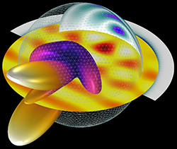
Figure 1 Simulated scattering properties of a 3D inflatable reflector structure.
For example, Figure 1 shows a small inflatable sphere structure with a radius of two wavelengths, partially plated with a conductive material. Simulation of this geometry requires more than 20 GB of memory to solve the full-wave equations using the finite element method. Analyzing the antenna accurately, including the effect of spillover, blockage from a feed horn and the secondary reflector, requires the full-wave equation. The calculated back-scattering, far-field radiation pattern shows the size is not big enough to generate a high gain beam pattern.
When the shape of an antenna is axially symmetric—for example, a parabolic satellite dish antenna, SATCOM inflatable antenna or circular or conical horn antenna with a corrugated dielectric lens—the entire 3D antenna geometry does not need to be modeled. The cross-sectional geometry information is sufficient to characterize antenna performance, such as the far-field radiation pattern, gain, directivity and impedance properties.
2D AXISYMMETRIC MODELING
When addressing a large antenna that is axially symmetric, the setup for the simulation becomes dramatically simple, requiring only the cross-sectional blueprint. The benefit of 2D axisymmetric modeling is the simplicity regarding the modeling configuration and computational cost.
Assume a reflector antenna with a radius greater than 20 λ and an axial feed circular horn antenna illuminating the reflector. Since the axial feed circular horn and parabolic reflector antenna are solids of revolution, the antenna can be simulated using the 2D axisymmetric formulation of the EM wave equation (see Figure 2).
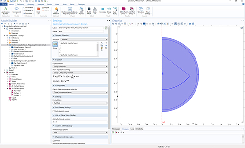
Figure 2 Multiphysics 2D model of a reflector antenna with axisymmetric geometry.
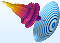
Figure 3 Simulated radiation pattern of a parabolic dish antenna.
Using a tutorial introduced with a recent update to the Multiphysics software, the metal surfaces are modeled as perfect electric conductors (PEC) and all domains are filled with air. The radius of the circular horn feed waveguide is 0.01 m and the cutoff frequency of the TE11 mode is approximately 8.8 GHz. The operating frequency of the antenna should be higher than the cutoff frequency. The horn aperture radius is 0.03 m, and the overall horn length is 0.06 m. A slit-conditioned interior circular port is assigned to the end of the waveguide to excite the antenna with the TE1m mode. The azimuthal mode number is set to one in the EM waves, frequency domain physics interface. The reflector is built using a 53 degree sector of a circle with a radius of 0.85 m. The conductive reflector body is removed from the model domain, where the EM wave cannot penetrate and, consequently, the PEC is automatically applied to its boundary. The model domains are enclosed by perfectly matched layers (PML) that absorb all the outgoing waves.
The far-field calculation boundary is specified to compute the radiation pattern. The mesh operation is performed based on the frequency used in the simulation (9.6625 GHz) via the physics-controlled mesh functionality in the RF Module, recently upgraded to handle frequency-dependent materials by way of interpolation functions. Through the physics-controlled mesh, the maximum mesh element size is set to 0.2 λ (five elements per wavelength) to ensure sufficient resolution of the wave. The PMLs are swept along the absorbing direction. With the relatively low degrees of freedom compared to a 3D model, the simulation takes less than 30 s to compute the S-parameter and far-field radiation pattern (see Figure 3).
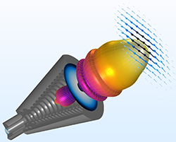
Figure 4 Corrugated horn antenna simulation for minimizing the cross-polarization on the aperture.
3D ANALYSIS OF THE 2D AXISYMMETRIC SIMULATION
Post-processing the results in 3D takes advantage of the top-notch post-processing functionality included in the RF Module, which is more powerful with each new version release.
In a 3D model, the feed horn is excited by TE11, the dominant mode of a circular waveguide, while the 2D axisymmetric formulation with TE1 mode has the temporal and angular dependence of an exponential function defined by the azimuthal mode number m. Since the field propagates predominantly in the +z direction of the cylindrical coordinate, positive and negative values of m correspond to right-handed and left-handed circular rotation, respectively. A linear superposition of the m = +1 and m = -1 solutions leads to the 3D solutions excited by the TE11 mode, allowing examination of the cross-polarization to compare the linear polarization in the x and y directions at the exit of the horn (see Figure 4).
FAST AND ACCURATE
Efficient modeling techniques with low computational cost and fast computational speed are critical for modern-day design and simulation of mmWave applications. The purpose of simulation is to describe real world devices and components as closely as possible through mathematical representation. When simulating and analyzing axisymmetric objects, such as spheres, conical dish antennas and circular waveguides, 2D axisymmetric modeling offers orders-of-magnitude faster computation compared to a full 3D model.
Simulating a simple-shaped structure may appear to be easy and fast without considering the impact of the electrical size of the model, in terms of wavelength. It is feasible to simplify the simulation process without losing accuracy with the support of 2D axisymmetric modeling, while sustaining the integrity required to analyze electrically large real-world components.
COMSOL Inc.
Burlington, Mass.
www.comsol.com