
A compact and cost-effective alternative to bulky and expensive test equipment has been the dream of many an engineer. Elite RF, a Chicagoland designer and manufacturer of power amplifiers and systems, tasked its engineers to develop a multi-purpose RF test equipment product that would be a workhorse for the RF engineer. The goals were to be as versatile as possible, have a small footprint—yet remain affordable compared to the typical RF test equipment on the market. The S-Series product line is the result of that development.
Test Bench in a Box
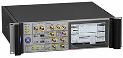
The S-Series is a general-purpose, all-inclusive RF test bench in one enclosure, a product that can be used for R&D characterization on the bench, EMC assessment and automated production test in the factory. The SPA1241 comprises a 12.4 GHz spectrum analyzer, 12.4 GHz RF tracking generator, 13.6 GHz dual signal generator, 18 GHz RF power amplifier, 200 MHz four-channel oscilloscope and 10 GHz RF power meter—in one piece of equipment. The RF equipment built into the S-Series can be used stand-alone or with other external equipment.
All of the instruments are accessible through front-panel connectors, except for the oscilloscope, which is accessed from the rear panel. Instrument settings are controlled with a wireless keyboard and mouse, which are provided with the instrument. The unit has Ethernet, USB and Wi-Fi interfaces and an HDMI connector on the rear, to connect an external monitor, which allows viewing multiple instrument displays at the same time. The Ethernet and Wi-Fi interfaces enable connection to the internet to access data sheets, test specifications and other documents during testing.
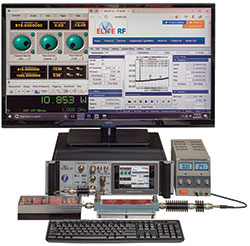
Figure 1 Testing a 900 MHz, 65 W power amplifier.
The system software, built on a general-purpose PC platform running Windows 10, allows independent control of the instruments. Each instrument has a unique software application that runs on the PC and can work with other software on the PC. As one example, a Labview test program developed for the system, block or circuit being tested can automatically control the internal instruments to provide a unique RF test environment. The Labview environment can be viewed and controlled using the monitor (internal or external), keyboard and mouse.
Power for the instruments and integrated power amplifiers (depending on the model) is provided from modular power supplies and a centralized power distribution circuit board. The power supplies are compatible with 100 to 240 VAC power lines.
CAPABLE AND FLEXIBLE
A few examples illustrate the versatility of Elite RF’s S-Series to test, measure and analyze:
Power Amplifiers: Power amplifier testing uses the signal generator, spectrum analyzer and power meter, as shown in Figure 1. The measurement setup only requires the S-Series product and a power supply and external pads for the amplifier being tested. In this example, the harmonic performance of the amplifier, which is putting out 10 W at 915 MHz, is measured with the spectrum analyzer. While all the measurement windows—signal generator, power meter and spectrum analyzer—are open and tiled on the external monitor, the display can be configured to show only one of the instruments, such as the spectrum analyzer for a closer view of the amplifier’s harmonics.
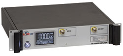
Figure 2 M-series 500 to 2500 MHz, 25 W power amplifier.
Setup and Calibration of an Amplifier: In this example, the S-Series is used to calibrate an M-Series power amplifier (see Figure 2), which covers 500 to 2500 MHz and provides 25 W output power. The M-Series power amplifier can be calibrated using the built-in functions of the S-Series. To calibrate the power and detected voltage across the frequency band, the test setup uses the signal generator and power meter with a custom program written to store the detected voltage versus power and frequency in the M-Series memory. The RF switching relay routes the RF output of the M-Series amplifier to either the S-Series power meter or spectrum analyzer. The power meter measures the output power and gain, and the spectrum analyzer measures the harmonic and spurious signal levels.
Scalar Network Analysis: The spectrum analyzer and tracking generator can be combined to create a scalar network analyzer, to measure the insertion loss of a filter, attenuator or amplifier (see Figure 3). Used with a directional coupler, this test setup also measures return loss.
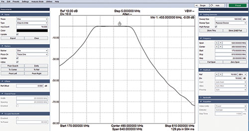
Figure 3 Scalar measurement of a bandpass filter.
Phase Noise: In the phase noise measurement mode, the spectrum analyzer displays the single-sideband phase noise on a logarithmically-scaled spectrum plot (see Figure 4).
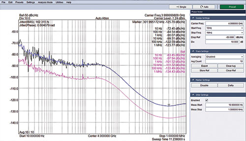
Figure 4 Phase noise measurements of a signal generator at 1 and 4 GHz carriers.
Digital Demodulation: The S-Series also has the capability to demodulate a digitally-modulated RF signal by using the spectrum analyzer as a vector signal analyzer (VSA). Complex communications signals that cannot be described as AM or FM (see Figure 5) can be characterized. The built-in software offers common VSA views, such as constellation diagrams, symbol-error charts and symbol tables and the system software demodulates ASK, BPSK, DBPSK, QPSK, DQPSK, 8PSK, D8PSK, π/4 DQPSK, OQPSK, N-FSK and 16-QAM.
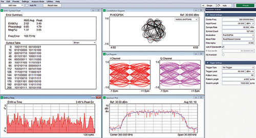
Figure 5 Demodulating a digital communications signal using the spectrum analyzer as a vector signal analyzer.
Elite RF’s innovative S-Series Multi-Purpose RF Test System fulfills the need for a cost-effective and compact alternative to a cluttered test bench. The S-Series, made in the U.S., is sold with a two-year warranty.
Elite RF
Hoffman Estates, Ill.
www.eliterfllc.com