
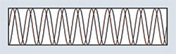
Figure 1 Phase coherency at the same frequency.
With rapid advancements in the areas of RF components and subsystems, and high-density digital signal processing electronics, multiple input multiple output (MIMO) technologies are receiving high attention for their capabilities to increase the data rates through multiplexing, or to improve the system performance by an order of magnitude or more through spatial diversity. Engineers are employing MIMO systems in a wide range of electronic warfare and radar applications ranging from phased array radars to beamforming and direction finding systems.
However, such MIMO systems must overcome key technical challenges related to channel-to-channel phase and amplitude synchronization to coherently receive and process the data acquired or generated from each input/output. The precise phase and amplitude synchronization of each channel poses serious challenges to testing and verification of multichannel phase-coherent systems. To efficiently test these systems, it is mandatory for test and measurement equipment to provide equal or better precision in signal coherence, and complete control over phase, time, frequency and amplitude.
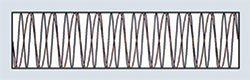
Figure 2 Phase coherency at different frequencies.
This article will provide an overview of the challenges and requirements for testing a multichannel phase-coherent measurement and generation system and review how these requirements map to test instrument design specifications. Additionally, the article will look at the actual steps needed to develop a multichannel phase-coherent test system from commercially available software-defined modular instruments, and discuss the details of a real-time calibration process for fine-alignment in phase and amplitude. Finally, an example of a next-generation multichannel phase-coherent test system including tests performed to validate that the system meets the requirements will be studied.
Phase coherency is an attribute of two or more waves where the relative phase is constant during the resolving time of the observer.1 Figure 1 shows conceptual diagrams of phase coherency of two channels with same frequency. Figure 2 shows the coherency for two channels with different frequencies, where the signals are at a specified phase relationship at every N cycles. After achieving phase coherence, the constant phase difference between the coherent signals can be compensated for by using phase alignment methods1.
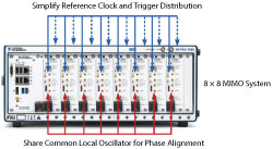
Figure 3 8 × 8 MIMO configuration with NI PXI VST.
In practical MIMO test systems, the radio hardware should be capable of acquiring and generating phase-coherent and phase aligned signals across the multiple channels. Many modern electronic warfare systems utilize a multichannel phase-coherent system for tasks such as direction finding in passive radar systems, or providing multipath redundancy in jamming-resistant communications. For example, phased array radars use hundreds of phase-coherent transmit/receive (Tx/Rx) modules to provide rapid electronic beam steering, where the relative phases of the respective signals feeding the elements are varied in such a way that the effective radiation pattern of the array is reinforced in desired directions and suppressed in undesired directions.2
Geolocation systems such as interferometric synthetic aperture radar (InSAR) employ several phase-coherent receivers to detect the location of events such as earthquakes and floods by precisely determining the position of a transmitted or reflected signal. In addition to the increased complexity of the design, the requirements of tight synchronization and fine-alignment in a multichannel phase-coherent system are some of the most stringent test requirements in the aerospace and defense industry.
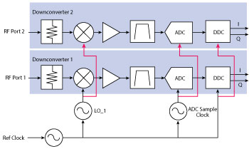
Figure 4 2-channel phase-coherent RF vector signal analyzer.
The primary challenge to building a test system for multichannel phase-coherent systems is the phase alignment of the coherent signals. Further, the systems need to be able to sustain the phase coherence and alignment over considerable time. However, drifts will occur, owing to effects like temperature, thermal expansion, mismatched cable lengths, uncorrelated phase noise, ADC sample clock, phase noise and quantization noise. At microwave frequencies, even small differences between cable lengths, amplifier devices and filters can create delays or phase shifts that destroy the desired relationships.
Phase stability of components, non-linear AM/PM effects and group delay variations can make phase matching a concern for the multichannel designer. Many applications in the direction finding and beamforming sectors demand that the phase relationships between channels be constant over time with minimal deviations, which may be as little as one degree or less phase drift.
TESTING MULTICHANNEL PHASE-COHERENT SYSTEMS

Figure 5 Comparing shared LO vs. 10 MHz reference: channel-to-channel skew (a) and histogram of channel-to-channel phase offset (b).
The following section will discuss the techniques to address the challenges of developing a test system for multichannel phase-coherent systems, using a modular software-designed instrumentation approach. The first challenge to overcome in a multichannel system is ensuring that all channels start acquiring or generating at the same time by creating a consistent and reliable triggering mechanism. Often, alignment between channels is required to have less than a nanosecond of difference, and cabling frequently proves an obstacle to achieving this. Long cables within test systems add a significant amount of propagation time to triggers, around 5 ns per meter of coaxial cable, so there is a need for simplification of trigger distribution.
Distributing the necessary clocks and triggers to achieve multi-device synchronization can be challenging because of the latencies and timing uncertainties caused by skew and jitter. A PXI-based platform for modular instruments is well suited to address these complexities. The PXI architecture allows designers to implement advanced multi-device synchronization by using unique features of PXI, such as the trigger bus, star trigger and a common system reference clock.
One method of synchronization is NI-TClk, in which another clock domain is used to enable alignment of sample clocks and the distribution and reception of triggers.3 Designers of multichannel phase-coherent test systems can use this method to align the sample clocks that are not aligned initially, despite being phase-locked to a common reference clock, and to enable the accurate synchronous triggering of the individual devices.
Figure 3 shows an 8 x 8 MIMO configuration of eight vector signal transceivers (VST), each capable of generating and acquiring 1 GHz instantaneous RF bandwidth in a single 18 slot chassis, tightly synchronized with a typical skew less than 500 ps using NI T-Clk and a shared PXI reference clock.
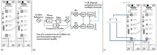
Figure 6 Two-channel phase-coherent test configuration (a), configuration with shared LO, common reference clock and T-Clk alignment (b) and calibration setup (c).
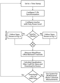
Figure 7 Multichannel phase-coherent calibration process.
ACHIEVING PHASE COHERENCE AND ALIGNMENT
Most traditional RF instruments, analyzers or generators allow reference clocks (usually 10 MHz) and occasionally a start trigger to be shared. While sharing these clock signals is sufficient to guarantee simultaneous signal acquisition and generation, it does not guarantee phase coherence. For example, consider the case where only a 10 MHz reference clock is shared between two vector signal analyzers.
In this scenario, the two analyzers will independently derive their local oscillators from a common 10 MHz clock. Over a short interval, signals may appear to have a constant phase difference, but over time the phase of each channel will drift. This is because each LO is derived independently from a 10 MHz reference, and the phase-locked loop (PLL) noise that is introduced when synthesizing each LO will be independent from one channel to the next. As a result, a multichannel RF system with only a shared 10 MHz reference will be characterized by substantial channel-to-channel phase skew.
A better approach to phase coherence and alignment is to derive a single LO for all channels from a single PLL, as shown in Figure 4. When the LO is directly shared, each downconverter shares the same phase noise.4
In Figure 5a, observe the channel-to-channel skew when using two different synchronization approaches. The blue trace shows the phase difference over time when each analyzer shares only a 10 MHz reference clock and does not share the LO. The red trace illustrates the phase difference between each channel when the local oscillator is shared directly between each downconverter signal chain. Note from the graph that sharing the LO directly enables significantly tighter phase alignment than when merely sharing a 10 MHz reference.

Figure 8 DSP architecture with equalization filter.
Another way to measure the benefit of sharing the LO directly is to look at a histogram of the channel-to-channel phase error, as shown in Figure 5b. In the case, where only the 10 MHz reference is shared, a relatively wide spread of phase variation (greater than one degree for six sigma confidence) is seen. In the case where the LO is shared directly, the same confidence level is within 0.2 degrees.

Figure 9 DSP architecture with pass-through filter.
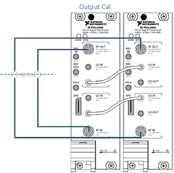
Figure 10 Calibration setup for phase-coherent generators.
REAL-TIME IN-LINE PROCESSING
Real-time processing is important for many aspects of testing electronic warfare systems. For test applications involving beamforming or direction finding, such as passive radar, it is important to calculate channel matrices in real-time, since channel characteristics change rapidly. Moving RF samples to a host processor would be slow, consuming both data processing capability and bus bandwidth. Instead, the samples can be moved to the on-board FPGAs or transferred through the high-bandwidth PXI bus to additional FPGA co-processors for in-line signal processing.
For many test applications, it can be equally important to store and play back signals. Storage of waveforms allows for in-depth observation of multichannel data, and enables the capture of spurious signals that may not occur for very long or often. Storage can also be valuable for retaining evidence of RF activity at specific geographies and times for surveillance of unauthorized signals or sporadic jamming. Real world signal capture can also be used to verify whether future communications systems will be resilient to real world scenarios.
The PCI Express architecture enables these requirements by supporting peer-to-peer transfers between multiple devices so that data can be continuously transferred and processed in real-time, or stored to disk for extended periods and post-processed. Such a system gives researchers and developers the ability to acquire and store information from multichannel RF sources for careful observation or offline processing. Later, in the lab, the data can be manipulated and played back as a stimulus signal for validating algorithms, channel models, hardware configurations and other aspects of real world systems.
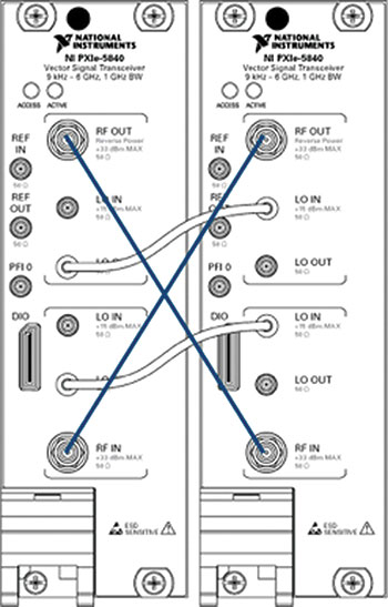
Figure 11 Verification of phase coherence after calibration.
Whether stationed in a lab or deployed in the field, size, weight and power (SWaP) are important considerations for measurement equipment in electronic warfare applications. With the increasing complexity and computational power requirements of advanced EW systems, designers are optimizing for SWaP requirements by creating multifunction systems that leverage the advancing technology and modular nature of the PXI platform.
MULTICHANNEL PHASE-COHERENT TEST SYSTEM
The next section looks at building a test system that can address the challenges and requirements of testing and verification of multichannel phase-coherent RF systems. This test system is built on a platform-based approach of modular hardware and software-defined instrumentation.
Figure 6a shows the configuration of an NI two-channel phase-coherent test system, which is configured in the PXIe-1085 chassis, an 18-slot chassis with built-in 10 MHz reference clock, PXI Trigger bus and star trigger for PXI modules. For RF instrumentation the PXIe-5840 VST is used in a 2 x 2 MIMO configuration.
Following are the steps to develop a multichannel phase-coherent test system.
Step 1: The first step is to configure the two VSTs to share a common PXI reference clock derived from the PXIe-1085 chassis via software, and to physically share the LOs between the generators and the analyzers, as shown in Figure 6b. The VSTs natively support NI-TClk technology, which ensures that all the channels start acquisition/generation simultaneously and can achieve a channel-to-channel skew typically less than 500 ps. We further enhance this by performing an in-system calibration which will further reduce skew another order of magnitude to less than 50 ps.
Step 2: Now that the VSTs are synchronized, the next step is to ensure the phase and amplitude coherence. For the sake of this example, there is multichannel phase coherence between the analyzers at first. In this step, one of the two VSTs is used as the source of the continuous wave signal that will be used as the calibration tone. The signal from the source is split using a two-way splitter, and fed to the RF input ports of the two VSTs, as shown in Figure 6c.
Step 3: The next step is to apply the FPGA-based real-time calibration process for fine-alignment of phase and amplitude between the two VSTs.5 This calibration process is implemented with the on-board Xilinx Virtex 7 FPGAs of the VSTs using LabVIEW FPGA. Figures 7, 8 and 9 describe the steps involved in the calibration process. This algorithm is scalable from two-channel to eight-channel configurations. MeasSys represents the multichannel phase-coherent acquisition system, Timestamp represents the initial time instance of measurement, freq represents frequency of CW tone and cal Validtime represents the duration of time after which the system needs to be recalibrated.
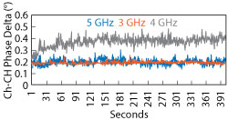
Figure 12 Average channel-to-channel phase difference vs. time.
Step 4: Now that the system is ready for multichannel phase-coherent measurements, the next step is to configure a multichannel phase-coherent generation system. Figure 10 shows the hardware configuration for this step, where the two VSTs are simply connected in the loopback mode with shared LOs and a common reference clock.
Step 5: The next step is to apply the real-time calibration process for the fine-alignment of phase and amplitude difference between the generator. Repeat the process described in Step 3 to achieve a multichannel phase-coherent generation system.
Step 6: Now, the next-generation system for testing a multichannel phase-coherent RF system is ready for use. This can be simply verified by connecting the two VSTs in a crisscross method, as shown in Figure 11, and then observing the stability in phase and amplitude difference over time.
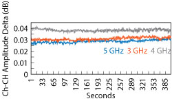
Figure 13 Average channel-to-channel amplitude difference vs. time.
The multichannel phase-coherent test system was tested in a chamber with regulated temperature conditions. The phase and magnitude difference was calculated between the two channels after applying the calibration algorithm, and the measurements were taken at three different frequencies of 3, 4 and 5 GHz, as shown in Figures 10 and 11. Note that the plots, Figures 12 and13 show the average phase and magnitude difference between two channels. The results suggest that the next-generation multichannel phase-coherent test system built as described effectively achieved a phase difference with less than ±1 degree variation, and magnitude difference within 0.05 dB variation sustained over time.
CONCLUSION
With multichannel phase-coherent systems becoming more common in electronic warfare and radar applications, the need to efficiently test and deploy such systems is becoming increasingly significant. Further, it is a critical requirement for a test and measurement setup to offer equal or better precision in phase and amplitude alignment in the multichannel RF systems.
This article considered the challenges and requirements of testing a multichannel phase-coherent system, presented a next-generation test system that addressed these challenges using a platform-based approach and outlined a software-defined FPGA-based calibration process that allows for sustained phase coherence with an internal calibration mechanism.
Results were presented to demonstrate the stability in phase and amplitude variations of the multichannel phase-coherent test system. With the scalable and modular nature of the PXI platform, the proposed architecture for the two-channel phase-coherent VST system can be further scaled to achieve 4 x 4 or 8 x 8 phase-coherent test systems with a consistent precision in phase and amplitude variations.
References
- D. Hall, A. Hinde and J. Peg, “Multichannel Phase-Coherent RF Measurement System Architecture and Performance Considerations,” in Proc. 2014 IEEE Military Communications Conference (MILCOM), pp. 1318-1323, 2014.
- J. Hutmacher, “Phase-Coherent Test Systems for Multi-Receiver Applications,” Defence Electronics, www.defenseelectronicsmag.com/site-files/defenseelectronicsmag.com/files/archive/rfdesign.com/mag/agilentdef.pdf.
- K. Wagle, “Essential Synchronization Technologies in PXI,” PXI Technology Review, 2014, www.download.ni.com/pub/devzone/tut/pxitecharticle.pdf.
- NI White Paper, “Configuring Phase-Coherent RF Measurement System: From MIMO to Beamforming,” National Instruments, www.ni.com/white-paper/9127/en/.
- S. Chaudhary and A. Samant, “Characterization and Calibration Techniques for Multichannel Phase-Coherent Systems,” IEEE Instrumentation and Measurement Magazine, 2016, www.ieeexplore.ieee.org/document/7524208.