
Satellite and radio waveforms can utilize custom/proprietary formats with modulation bandwidths beyond 1 GHz for increased data rates. Generating custom waveforms with wide modulation bandwidths can present challenges, especially when excellent signal fidelity is required and when distortions must be kept to a minimum. Traditional signal generators can provide the required signal purity, but are limited in modulation bandwidths. In addition, wide bandwidth signal analysis requires a new approach for waveform demodulation relative to a traditional RF signal analyzer approach.
These challenges highlight the need for an improved wideband waveform generation and analysis methodology. This article will show a new waveform generation solution, using a wide bandwidth, high precision arbitrary waveform generator (AWG), combined with a vector RF/microwave signal generator with wideband IQ inputs to generate a 16QAM waveform at X-band with a 1.76 GHz symbol rate. Simulation will provide the flexibility needed to create custom/proprietary AWG waveforms. A 32 GHz high performance digital oscilloscope with vector signal analysis (VSA) software will be used to demodulate the waveform to measure the error vector magnitude (EVM).
A Paradigm Shift for Wide Bandwidth Applications
RF signal generators have traditionally been used for wireless applications. They typically offer good signal purity and performance and the convenience of software applications, which can be used to generate parameterized and pre-configured waveforms, such as Mobile WiMAX™ and LTE. However, RF signal generator AWG modulation bandwidths are typically limited to approximately 100 MHz, which can limit their ability to address emerging applications, such as wide bandwidth satellite and radio communications. In these communication systems, modulation bandwidths may significantly exceed 100 MHz and possibly even approach 1 to 2 GHz of modulation bandwidth. In addition, military radio applications, such as software defined radio (SDR), may require custom waveforms to be generated, such as a custom orthogonal frequency division multiple access (OFDMA) waveforms. Flexibility is needed in the waveform generation process to facilitate custom proprietary waveform creation, in addition to wide modulation bandwidths.
A similar situation exists for RF signal analysis. Today's RF signal analyzers have IF bandwidths of approximately 140 MHz, which can limit modulation domain analysis, or waveform demodulation, to applications where the modulation bandwidth is within 140 MHz. A new approach is needed for RF/microwave modulation domain signal analysis applications, which exceed 1 to 2 GHz of modulation bandwidth at X-, Ku- and Ka-band carrier frequencies.
High performance commercial-off-the-shelf (COTS) AWGs and digital oscilloscopes are an enabler for wide bandwidth RF/microwave applications. Recent breakthroughs in their performance present a paradigm shift in the way RF engineers think about creating and analyzing wideband satellite and radio waveforms over traditional approaches.

Figure 1 Spectral purity of high performance arbitrary waveform generator.
For example, take the spectral purity of a high performance AWG, as shown in Figure 1. The AWG is used to generate a simple single tone at 555 MHz with a sampling rate of 7.2 giga samples per second (GSa/s). The spectral purity is clean, with spurious down to approximately -86 dB. Of course, although this CW case shows the performance that can be achieved with a wideband AWG, it is not representative of the modulated signal formats used for satellite and radio applications.
The next section of this article will show the waveform creation and analysis of a 16QAM waveform at X-band with a 1.76 GHz modulation bandwidth. The residual error vector magnitude (EVM) will be used as the metric, to show the high performance that can be achieved with today's AWG and oscilloscope COTS technology.
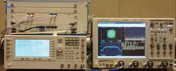
Figure 2 COTS test equipment setup to generate and analyze wide-band satellite communications and radio waveforms.
A 16QAM Example Using a Wide Bandwidth COTS Test Setup
Figure 2 shows the high performance wide bandwidth COTS test equipment used to generate and analyze a 16QAM waveform at X-band with a 1.76 GHz modulation bandwidth. The upper left is a precision wide bandwidth AWG with a DAC resolution of 14 bits up to 8 GSa/s, or 12 bits up to 12 GSa/s. The AWG has 2 GSa of arbitrary waveform memory per channel and 5 GHz of analog bandwidth per channel. This is the AWG used to generate the CW tone in Figure 1, but here it is being used to generate a wideband 16QAM waveform. A vector signal generator with wideband IQ inputs is shown on the lower left. This is used to modulate the IQ waveform on an X-band carrier centered at 10 GHz.
A high performance 32 GHz digital oscilloscope, with VSA software, is connected to the signal generator output to demodulate the wideband 16QAM waveform at the RF/microwave carrier frequency. Although oscilloscopes are traditionally used for time-domain measurements, here it is being used for RF/microwave frequency modulation domain analysis.

Figure 3 Diagram of the test equipment setup.
Figure 3 shows the setup diagram of the test equipment shown in Figure 2. Waveform creation software or simulation software, such as MATLAB™, can reside on an external PC and downloaded to the AWG. However, in this example, it is installed in the oscilloscope and downloaded from the oscilloscope to the AWG via LAN.

Figure 4 Configuring a MATLAB utility to generate and download a 1.76 GHz 16 QAM waveform to an M8190A AWG.
The differential analog IQ outputs of the AWG are fed into a vector RF/microwave signal generator with external wideband IQ inputs, to modulate the IQ waveforms onto a 10 GHz carrier. The output of the vector signal generator is connected to channel 1 on the high performance digital oscilloscope to demodulate the waveform. However, before generating the 16QAM waveform, a MATLAB utility is first used in the digital oscilloscope to create and download a wideband multi-tone waveform for flatness corrections (see Figure 4). The complex frequency response (magnitude and phase) of the AWG output path, in combination with the I/Q modulator in the vector PSG, are analyzed using the VSA software in the oscilloscope. This information is fed back into the MATLAB script, which calculates a pre-distorted waveform and downloads it into the AWG.

Figure 5 Measurement results for a 1.76 GHz 16 QAM waveform at 10 GHz.
Once flatness corrections have been performed, a MATLAB utility is then used to create and download the 16QAM waveform from the oscilloscope to the AWG via LAN. The digital modulation dialog box is configured for a 16QAM waveform with a 1.76 GHz symbol (modulation) rate and 4× oversampling (7.04 GSa/s sample rate). A 0.35 alpha root raised-cosine filter is applied. The high performance digital oscilloscope with VSA software is then used to demodulate the resulting RF/microwave wideband waveform as shown in Figure 5.
The 16QAM constellation is shown on the upper left of the VSA display, the RF modulated spectrum centered at 10 GHz is shown on the lower left, the EVM vs. symbol (time) is shown on the upper right, and the EVM summary table is shown on the lower right. The residual EVM is measured at approximately 1.17 percent, which is quite impressive for a modulation bandwidth of 1.76 GHz at a 10 GHz carrier frequency. Using the VSA software with wide bandwidth high performance digital oscilloscopes enables RF engineers to analyze wide bandwidth modulated waveforms at X-, Ku- and Ka-band (up to 32 GHz) directly, without the need for external down-conversion. In addition, multiple phase coherent inputs enable multiple-input multiple-output (MIMO) OFDMA waveforms to be analyzed and demodulated,1 using the digital oscilloscope with VSA software. Although not shown in this example, MATLAB can also be used as a custom user defined function (UDF) in digital oscilloscopes.2
Summary
An improved approach for generating and analyzing wide bandwidth waveforms for satellite and radio applications was shown. High performance precision AWGs, combined with RF/microwave vector signal generators with external wideband IQ inputs, enable RF engineers to generate wideband waveforms with excellent signal fidelity. Simulation tools, such as MATLAB, facilitate creating and downloading custom/proprietary waveforms using COTS equipment. High performance digital oscilloscopes, combined with VSA software, enable wide bandwidth RF/microwave waveforms to be analyzed at X-, Ku- and Ka-band, up to 32 GHz, without the need for external down-conversion. Exceptional residual EVM performance was demonstrated with the AWG, vector signal generator and digital oscilloscope on a 10 GHz X-band waveform modulated at a 1.76 GHz symbol rate.
References
- "Solutions for MIMO RF Test and Debug- Ensuring Quick and Accurate Four-Channel, Phase-Coherent MIMO Measurements," Agilent Application Note, www.agilent.com/find/powerofx.
- "Wideband Radar and Satcom Measurements Using Wide Bandwidth Oscilloscopes to Directly Measure and Analyze X, Ku, and Ka-band Radar and Satcom Transmitter Outputs up to 32 GHz," Agilent Application Note, www.agilent.com/find/powerofx.
"Mobile WiMAX" is a registered trademark of the WiMAX Forum. MATLAB is a registered trademark of The MathWorks Inc.
Greg Jue is an Applications Development Engineer/Scientist in Agilent's High Performance Scopes team. Previously he was with Agilent EEsof Electronic Design Automation (EDA), specializing in SDR, LTE and WiMAXTM applications. He pioneered combining design and test solutions at Agilent Technologies and authored the popular application notes 1394 and 1471 on combining simulation and test. Before joining Agilent in 1995, he worked on system design for the Deep Space Network at the Jet Propulsion Laboratory, Caltech University.
Thomas Dippon works as a Strategic Product Planner for pulse-, function- and arbitrary waveform generators. In almost 20 years with Agilent/HP, he has held several positions in R&D, technical support and project management. He is based in Boeblingen, Germany.