PTFE (Dupont’s Teflon®) has been the transmission line dielectric of choice for several decades; however, PTFE undergoes a material phase change at room temperature. It undergoes a virtual “step function” volumetric change and a change in relative permittivity as well as having a “hysteresis” effect on changes in electrical length. These variable material properties and changes in electrical length can be difficult to reliably predict and account for via system software or other means and may contribute to systematic performance degradation. Developments in dielectrics, using both organic and inorganic materials, have yielded dramatic improvements in performance relative to temperature. This article compares and contrasts several coaxial cable technologies for electrical length change as a function of temperature, electrical length tracking of multiple cables as a function of changing temperature, electrical length tracking of multiple cables when transiting through diverging thermal zones and electrical length repeatability versus multiple iterations of temperature cycling. Additive phase noise as a function of mechanical vibration and interactions between conductors and dielectric materials, as they pertain to electrical length parameters, will also be discussed.
Oliver Heaviside noticed that wrapping a telegraph wire in an insulator improved both the signal quality and effective range of communications signals. In 1880 he patented the world’s first coaxial cable. In 1931 engineers at AT&T’s Bell Telephone Laboratories patented the first modern coaxial cable. Crude by today’s standard it was constructed of two concentric metal tubes separated mostly by air.
In the 1930s gutta percha (a natural form of rubber) was the primary dielectric of choice for early flexible coaxial cables. Polyethylene became the predominant insulator of choice during the World War II years. In the 1950s, “foaming” processes were developed that reduced cable capacitance and loss characteristics.
In the 1960s, solid, full density polytetroflouroethylene (PTFE), or “Teflon®” gained widespread use. Its higher temperature ratings, lower loss tangent, lower dielectric constant and uniform properties over a wide range of temperatures and frequencies made it almost universally desirable as a coaxial cable dielectric.
In the 1970s and 80s manufacturers began using expanded, low density versions of PTFE to further improve its desirable properties. In the 1990s an increasing demand for electrical length stability drove manufacturers to begin using ultra low density PTFE dielectrics. These products were a definite improvement but still had some inherent limitations. Chief among these was a phase vs. temperature “knee”; a step function change in electrical length caused by the base material properties of PTFE molecules. This effect can be minimized but is impossible to eliminate.
In 2004 PhaseTrack® coaxial cable products using TF4® fluorocarbon dielectric technology were introduced to specifically address this problem. In 2015 further refinements and process developments have culminated in an improved TF4 technology with some very clear advantages over PTFE dielectric material in phase sensitive applications.
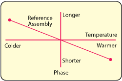
Figure 1 Temperature effect on coaxial cable electrical length.
PERFORMANCE METRICS
The ideal microwave cable assembly has zero loss, zero reflected energy and zero electrical length across all environmental conditions that system components would ever see. In our practical world we endeavor to come as close to the ideal as possible. This is certainly true with regard to electrical length changes of a coaxial cable assembly as its surrounding temperature changes.
Phase Change as a Function of Temperature
It is commonly known that the metals used to construct coaxial cable assemblies have positive temperature coefficients of expansion and that electrical length and physical length are directly related. It would seem obvious that with an increase in temperature an increase in physical length and thus an increase in electrical length would follow.
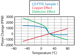
Figure 2 Temperature effect on phase in PTFE-based coaxial cable.
In fact, the opposite is true; most microwave cable assemblies exhibit negative temperature coefficients of electrical length, as represented by Figure 1. The axial lengths of the center and outer conductors increase directly with temperature. The diameter of the outer conductor increases as well, in a direct relationship with temperature, causing a small density change in the dielectric core that alters the net relative permittivity. The change in relative permittivity has an effect on electrical length that is opposite to that of the metal expansion/contraction. This is significant, as this phenomenon makes it theoretically possible to balance the two effects and achieve zero phase change with respect to temperature.
A practical cable assembly, using PTFE as a propagation medium, will always have a step function change in dielectric constant at room temperature with a corresponding change in electrical length. Figure 2 illustrates the temperature effect on phase. Copper has a positive temperature coefficient of expansion of 17 PPM/°C. For this construction the dielectric has a negative effect on electrical length of 23 PPM/°C. The dielectric also exhibits the PTFE phase transition “knee”.
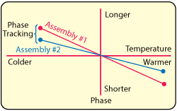
Figure 3 Phase tracking vs. temperature.
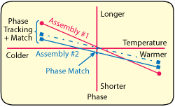
Figure 4 Phase tracking with initial phase matching.
Phase Tracking as a Function of Temperature
In practice, phase matched cable assemblies do not retain their relative phase match as temperature is varied. The degree to which they maintain their initial relative match is referred to as phase tracking. Figure 3 illustrates how two cable assemblies, initially phase matched at room temperature, might track as a temperature changes.
Several factors contribute to good phase tracking performance. Most critical is uniformity per unit length of cable, which includes capacitance, impedance and conductor mechanical uniformity. Worst case phase matching at all temperatures is a function of the initial match plus phase tracking characteristics (see Figure 4).
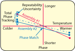
Figure 5 Total phase tracking over temperature is the combination of phase matching, phase tracking over temperature and repeatability. Phase noise can contribute to the uncertainty.
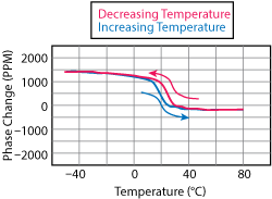
Figure 6 Hysteresis effect from the PTFE dielectric.
Phase Matching at Room Ambient Temperature
Cable assemblies that are intended for use in phase sensitive applications are phase matched. As environmental temperature changes occur, the ensuing phase change is proportional to the initial electrical length. Assemblies having the same electrical length, and subjected to the same temperatures should, ideally, maintain their phase matched characteristic. In addition to electrical and mechanical consistency, the degree to which a group of cable assemblies is initially matched factors into phase tracking performance.
Phase Repeatability as a Function of Temperature
Virtually all system applications are subject to dozens or hundreds of temperature cycles. It is important to know that each repetition of a specific temperature yields a consistent and repeatable electrical length. Semi-rigid cable tends to be the most reliable in this regard. Well made flexible cables can also be quite repeatable but they have inherent variability due to interactions between expanding and contracting dielectric cores and outer shields. Total phase tracking vs. temperature is the composite of phase matching, tracking over temperature, and repeatability (see Figure 5).
Phase Hysterisis as a Function of Temperature
PTFE has many characteristics that make it highly desirable as a cable dielectric material. A serious drawback, however, is the fact that it undergoes a molecular phase change between 18° and 20°C, further complicating cable phase vs. temperature characteristics with its hysteresis properties (see Figure 6). The phase change equates to a 1.5 percent volumetric change with a corresponding change in dielectric constant, resulting in an abrupt change in cable electrical length. This effect can be reduced by using a less dense PTFE dielectric, but it cannot be eliminated. In addition, the phase change begins at different temperatures for increasing vs. decreasing directions of temperature change, further degrading total phase tracking performance over temperature.
TYPICAL MICROWAVE CABLE PERFORMANCE
PTFE dielectrics are, by far, the most commonly used for the construction of microwave and millimeter wave cable assemblies. They are used mainly in two basic categories, full density (εr= 2.01) and low density (εr = 1.73). There are also ultra low density PTFE (εr = 1.42) cables optimized to the extent of which a phase stable cable can be constructed using PTFE. These cables tend to be highly prone to mechanical damage as the ultra low density construction provides very little mechanical support.
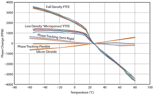
Figure 7 Phase vs. temperature “signature” of various coaxial constructions.
In general, the plastic density per unit length of expanded PTFE dielectrics has consistency variations that translate directly to phase tracking degradation. This is most prominent at the temperature extremes of the cables rated operating temperature. Figure 7 overlays the phase vs. temperature “footprints” of several high performance coaxial cable products.
Solid core, full density PTFE dielectric cables are very mechanically robust. The phase temperature slope is the highest of the variants and the effects of the molecular phase transition is pronounced.
Low density “microporous” PTFE dielectric cores are made in several ways all using variations of a similar process. Full density PTFE material is placed under tension and stretched under controlled conditions and at elevated temperatures. The material is cooled while under tension and the result is an “expanded” PTFE material that can be used to construct a cable dielectric core. These products likely comprise the bulk of cable used in phase sensitive microwave applications. The low density material minimizes the phase temperature slope as well as the “step-function” change in electrical length at the phase change transition temperatures.
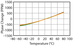
Figure 8 Typical phase vs. temperature of silicon dioxide semi-rigid coaxial cables.
PTFE ALTERNATIVES
Several alternatives to PTFE-based coaxial cables have been developed that exhibit significant improvement in system level performance. All of these eliminate the phase temperature “knee” allowing for improved balance of the conductor–dielectric effects on phase vs. temperature performance.
Silicon Dioxide Semi-Rigid Cable Assemblies
Silicon dioxide is a material that has been used as a cable dielectric for a number of years. The silicon dioxide material is extremely hygroscopic. As such, it must be used in cable assemblies that are fully hermetically sealed (leak rate less than 5 × 10⁻⁸ Atm-cc/sec He). These cable assemblies are semi rigid in construction using copper clad stainless steel jackets welded to stainless steel connector bodies. Given the consistent geometries of the cable and the inorganic nature of the dielectric, these cable assemblies display the ultimate in phase vs. temperature repeatability and tracking performance (see Figure 8). In addition, the materials employed in their manufacture produce extremely robust cable assemblies. The dielectric has the properties of compacted sand providing excellent support for the outer conductor when under mechanical stress. The stainless steel and silicone dioxide materials are both extremely radiation and corrosion resistant, as well. They are suitable for use from absolute zero to well over 600°C and have an impressive pedigree in aerospace applications.
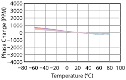
Figure 9 Typical phase vs. temperature of TF4 semi-rigid coaxial cables.
PhaseTrack Semi-Rigid Cable Assemblies Using TF4 Dielectric
A more recent development uses a flouropolymer blend dielectric developed by Times Microwave Systems. This material has similar temperature ratings as PTFE but does not have the abrupt shift in dielectric constant. Because it can be melt extruded it is much more consistent per unit length than expanded PTFE thus exhibiting improved phase tracking and repeatability. The semi rigid construction uses the same uniform tube structure as silicon dioxide cable assemblies, providing repeatability that rivals silicon dioxide cables without the need for stainless steel conductors and specialized connectors.
Another advantage is the “closed cell” nature of the dielectric core. To achieve a balance between conductor and dielectric effects, a low density PTFE dielectric core must be less dense than what is required to be mechanically robust; however, an ultra low density (velocity factor (Vf) = 84 percent) TF4 dielectric has the same durometer measurement as a standard density (Vf = 76 percent). This allows for a mechanically robust cable without the necessity of heavy and expensive mechanical strength members. Figure 9 shows the phase repeatability and tracking performance of semi rigid coaxial cable assemblies manufactured with the TF4 material.
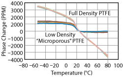
Figure 10 Phase vs. temperature of full density and low density PTFE flexible coaxial cables.
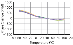
Figure 11 Phase vs. temperature “signature” of TF4 flexible coaxial cables.
PhaseTrack Flexible Cable Assemblies
Just as the TF4 dielectric provides a drop-in replacement for PTFE in semi rigid constructions it also provides similar benefits to flexible cables. These cables are sized similarly to PTFE cables. In addition they look and handle almost identically. The benefits are improvements in phase change with temperature, phase tracking with temperature and phase repeatability with temperature.
Figures 10 and 11 compare the phase versus temperature characteristics of flexible PTFE and TF4 cable assemblies. Each cable type includes 10 phase matched assemblies to offer not only a comparison of phase versus temperature characteristics but tracking characteristics as well.
PHASE PERFORMANCE
The overlay in Figure 7 of five cable technologies provides a comparison of the relative phase vs. temperature “footprint” of each type. It is evident that cable assemblies made using a dielectric core of solid PTFE have steep phase temperature slopes that become extreme at around room temperature. In the region between +15° and +25°C, the slopes are about -130 PPM/°C. This rate of electrical length change is more than four times greater than at cold temperatures below +15°C. Below room temperature, the temperature coefficient is -30PPM/°C.
A similar change in the phase temperature slope characteristic occurs with all PTFE based cable dielectrics. The magnitude of the slope change can be minimized by reducing the dielectric core density, but it can never be eliminated as it is a fundamental property of the PTFE material. The reasonably optimized “microporous” PTFE product illustrated in Figure 10 demonstrates this effect. The effect of the plastic properties is fairly well balanced against the effect of the expansion-contraction of the metals in the temperature ranges above and below the PTFE material phase transition temperatures. Phase versus temperature slopes are, therefore, relatively flat outside of the room temperature range. It demonstrates a reduced, but still significant phase vs. temperature slope between +15° and +25°C; the phase temperature slope in this zone is about -85 PPM/°C.
Several manufacturers offer products with “ultra” low density PTFE dielectric cores. These products have achieved propagation velocity factors in excess of 85 percent with further reductions in phase temperature slope in the room temperature region. They tend to over compensate the dielectric-conductor balance with a slight positive phase temperature slope above and below the PTFE “knee” and a further reduction in the electrical length slope within the material phase transition temperature band. The characteristics of these products are not discussed in this article as their dielectric cores are so mechanically fragile that they are impractical for all but the most benign applications. When the dielectric offers such little mechanical support it often gives way to mechanical degradation and associated structural return loss and stability problems.
Silicon dioxide and the TF4 dielectric technologies solve both problems without adding size or weight. They have been reasonably well optimized as far as the conductor-dielectric balance without any hint of a slope change at any temperature within the operating range. This is achieved with mechanical durability and handling properties equivalent to, or better than the low density microporous PTFE cable products.
Phase Tracking vs. Temperature
An important cable function is to maintain the relative electrical length relationships of multiple signal paths across an entire system operating temperature range. The degree to which cable assemblies “track” each other is especially critical in regions of the hardware architecture that cannot be calibrated or accounted for via other means. As a general rule the key property of a coaxial cable assembly as it applies to phase tracking is consistency per unit length of cable. Contributors to consistency include dielectric density per unit length, conductor consistency per unit length, material properties, conductor geometries and manufacturing process conditions.
From Figure 7, one can clearly identify two empirical trends. Each of the five examples is illustrated using 10 identical cable assemblies phase matched at room ambient temperature. Solid dielectrics track better than less dense dielectrics and semi-rigid assemblies track better than flexible constructions.
Figures 10 and 11 illustrate the improved tracking performance of the TF4 material over the micro porous PTFE. Both of the cable assembly types that produced the data were identical with the exception of the dielectric material. Both were standard flexible cable designs. The group of PTFE cables tracked to within ±200 PPM around a nominal phase temperature profile. The identically constructed TF4 cables tracked to within ±100 PPM.
When the wire weave “basket” construction of the outer conductor used in a flexible cable is replaced with a solid tube, the tracking performance is further improved to ±50 PPM. The silicon dioxide product, with its solid geometries, inorganic dielectric material and fully welded construction provides the ultimate in tracking performance at ±25 PPM.
Phase Repeatability vs. Temperature
A similar but subtly different attribute of phase temperature performance is phase repeatability. This is the measure of how well a cable returns to a given electrical length over the course of multiple iterations away from, and back to a given temperature. It is closely associated with phase tracking. In fact, without good repeatability, good tracking performance is just a statistical anomaly and a very unlikely event.
Figure 12 illustrates the phase repeatability of an ultra low density PTFE cable assembly and compares it to an identically constructed assembly using a TF4 dielectric. The chart plots the electrical length of the two assemblies, at -60°C, +30°C and +100°C. The red “constellation” of symbols is the PTFE assembly and the green is the TF4 assembly. At each temperature, the variance observed in the TF4 assembly is a fraction of the variance seen in the PTFE assembly. This is one of the attributes contributing to improved phase tracking vs. temperature of a bundle, or network of cable assemblies.
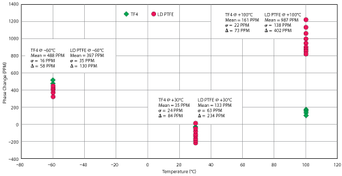
Figure 12 Phase repeatability vs. temperature of TF4 and PTFE coaxial cables.
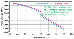
Figure 13 Phase tracking through mildly diverging temperature zones.
Phase Tracking vs. Diverging Temperature Zones
The previous discussions assumed that all parts of all the cable assemblies are held at the exact same temperature. In practice, this is virtually never true. Quite often cables will have slightly different routings through sections of hardware that are at different temperatures. As long as the cables are exactly matched at a given temperature they maintain their tracking. Once they transit to even slightly different temperature zones the tracking degrades. The larger the phase vs. temperature slope the greater the effect. Figure 13 quantifies the case for two full density PTFE cables in a ±2°C temperature environment. Assuming the overall system experiences the full environmental temperature range, and the thermal consistency of the system hardware results in a 4°C differential between the two cables, then there might easily exist an 800 PPM difference in electrical length between the two cable assemblies. For a lower density PTFE cable this value is reduced to approximately 500 PPM. Of course this maximum difference occurs at the environmental temperature where the phase temperature slope is steepest. It stands to reason that the flatter the phase temperature slope, the less sensitive system performance will be to slight “hot spots” within the system environment. Figure 14 provides a comparison of all the cable technologies discussed with respect to phase tracking with a 4°C temperature differential in the routing of two identical assemblies.

Figure 14 Comparison of phase tracking through divergent temperature zones.
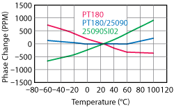
Figure 15 Technology blending to minimize phase change vs. temperature.
Product Blending
There may be circumstances where only the absolute minimum of phase change vs. temperature can be tolerated. In these cases technology “blending” techniques have been used with excellent results.
For example, the TF4 dielectric technology has a very slight negative slope in its phase versus temperature characteristic, while for the silicon dioxide technology there is a very slight positive slope. When two cable assemblies, one using TF4 semi rigid and the other using silicon dioxide semi rigid, are connected in series, their phase versus temperature slopes offset each other. The effect is proportional to the overall length of the combined pair. By adjusting the electrical lengths of the two assemblies, the phase temperature slope can be effectively cancelled. In Figure 15 the negative phase temperature slope of a TF4 semi rigid cable is combined with the positive phase temperature slope of a silicon dioxide cable. The result is a virtually flat phase versus temperature response from -40° to +60°C.
CONCLUSION
Excellent phase temperature performance is desirable in phased array antennas and other system architectures. It is also important in achieving and maintaining optimum test equipment calibration.
This is especially true in lab environments that are typically maintained in the worst temperature range for PTFE performance. Going from a cool room temperature to a warm room temperature can have a profound effect on phase sensitive measurements. Regardless of the application, when dealing with phase sensitive equipment it is important to consider the effects that even basic components may have on overall performance. While no existing technology can currently provide the ideal “transparent” interconnect there are more options than may be commonly known
