
A new very wideband mixer with integrated LO buffer and frequency doubler solves several challenging problems for microwave designers. The LTC5548 mixer eases design with the following key features:
- IF port, extending from DC to 6 GHz, eases wideband IF sampling
- On-chip LO limiting amplifier eliminates external LO buffer stage, reducing cost and minimizing total solution size compared to hybrid module solutions
- 0 dBm LO drive reduces total radiation leakage, reducing external filter and shielding requirements
- Ultra-wideband RF (2 to 14 GHz) and LO (1 to 12 GHz) ports are continuously matched.
The device has a wideband differential IF port that works from DC to 6 GHz. Its low frequency capability makes for more flexible frequency planning. The LTC5548 is ideal for receiving wideband signals, especially with bandwidths of 500 MHz to 1 GHz or higher.
Unlike most microwave mixers, which typically require a “hefty” +13 dBm or higher LO drive, the LTC5548 has an integrated LO buffer and only requires 0 dBm drive. Since the device starts with a 0 dBm signal, rather than the +13 dBm or higher typical with alternative devices, the LO leakage present at other ports is 13 dB lower. This results in much simpler filtering requirements, especially with the low IF frequencies the LTC5548 can support. The on-chip LO buffer significantly improves the RF to LO port isolation, which helps reduce any issues with frequency pulling of the synthesizer source due to a parasitic RF signal at the LO input.
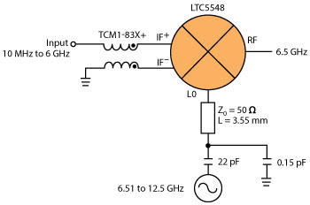
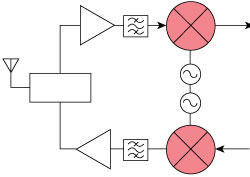
Figure 1 Up-converter design for converting a wideband, 10 MHz to 6 GHz IF to a constant 6.5 GHz RF output.
The LTC5548 is designed for wideband operation and can be used bidirectionally, either as an up-conversion or down-conversion mixer. Its RF port can be the input in a down-converting receiver or the output in an up-converting transmitter. Its RF port has an on-chip balun, enabling it to operate single-ended. The balun transformer is matched to 50 Ω continuously from 2 to 13.6 GHz, with better than 10 dB return loss.
To make the part truly useful for wideband applications, its LO port is also single-ended and is matched to 50 Ω continuously from 1 to 12 GHz. The 50 Ω impedance termination is constant, regardless of whether the LTC5548 is enabled or disabled, so switching the mixer on and off produces no disturbance that could unlock the phased-locked loop in the LO source. The 50 Ω ports greatly ease design for the microwave system designer. First, this makes for simpler filtering and interfacing to other parts of a 50 Ω system. Secondly, the extremely broadband match is far more forgiving to the circuit’s sensitivity to external matching component value variations, producing very consistent performance with system production variations.
The LTC5548’s LO port can be driven directly with a signal source to 12 GHz for best noise figure and spur performance. Alternatively, the port can be configured to use the internal frequency doubler; when selected via a digital select pin, up to a 6 GHz LO signal will be doubled internally to operate up to 12 GHz. This option facilitates the use of a lower cost, low frequency PLL/synthesizer. The trade-off is slightly higher noise figure and more spur components at the mixer’s input and output because the frequency doubler generates not only the harmonics of the desired LO frequency but also the harmonics of the half LO input frequency. The result is an extremely small size solution.
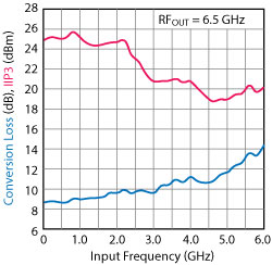
Figure 2 Conversion loss and IIP3 vs. input frequency, using high-side LO drive and the LO doubler off. TC = 25°C.
An example of a wideband transmitter application is shown in Figure 1. This circuit up-converts a 10 MHz to 6 GHz input signal, using a swept LO frequency of 6.51 to 12.5 GHz, to create a fixed 6.5 GHz RF output. To achieve such wideband input performance, a Mini-Circuits model TCM1-83X+ balun transformer is used to convert the single-ended input to the differential IF port of the mixer. With high-side LO injection, the mixer exhibits a relatively flat conversion loss from near DC to 3 GHz, as shown in Figure 2. Within any 1 GHz of input bandwidth below 5 GHz, the gain flatness is better than 1 dB. Once the input is pushed above 5 GHz, the conversion loss begins to change more rapidly. The input IP3 (IIP3) remains greater than 23 dBm from near DC to 2.5 GHz and is better than 19 dBm to 6 GHz. This example illustrates an extremely compact solution with minimal external components that requires only 0 dBm LO drive. The total solution cost is attractive, and an otherwise complex microwave circuit becomes much simpler and more manufacturable.
Housed in a tiny 2 mm × 3 mm plastic QFN package, the LTC5548 mixer is built on an advanced SiGe BiCMOS process with very consistent performance.
Linear Technology
Milpitas, Calif.
www.linear.com