
DARPA’s Mobile Hotspots Program seeks to provide high-bandwidth communications for troops in remote forward operating locations. The program goal is to demonstrate a scalable, mobile, self-forming and managing network of millimeter-wave air-to-air and air-to-ground gigabit class data links. The concept as depicted in Figure 1 is moving closer to a reality as the program progresses through Phase 2. It is a new, complex system that will maintain this network in the sky utilizing a fleet of small UAVs. Advanced millimeter-wave pointing, acquisition and tracking (PAT) technologies are needed to provide high connectivity among the UAVs and ultimately to the ground nodes.
The Mobile Hotspots Program sought to capitalize on the technology base already initiated by the allocation of the E-Band spectrum for telecom use which included both maturing and emerging technologies. The prospect of a viable military application drew wide interest from industry. Phase 2 of the Mobile Hotspots Program is now underway to carry forward the successes of Phase 1. Among these successes are new performance benchmarks for the millimeter-wave elements.
Millitech is on a team led by L-3 Communication Systems - West. Key technology advances at E-Band, as demonstrated by Millitech, are directly related to the underlying Phase 1 technical advances of BAE Systems and HRL Laboratories for their respective LNAs and GaN power device capabilities. In addition to L-3 (team lead), Millitech, BAE Systems, and HRL, other members of the team include MaXentric Technologies LLC with responsibility for software defined modem hardware (the waveform software itself is provided by L-3), IMSAR is managing the antenna pedestal, and Zivko Aeronautics Inc. is handling radomes and pod structures.
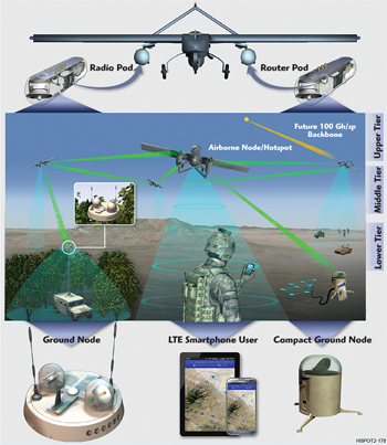
Figure 1 MHS conceptual diagram.
System/Subsystem Overview
The Mobile Hotspots airborne segment (see Figure 2), is being designed to operate on the SRQ-7 UAV platform commonly known as the Shadow. The Shadow is a “small” UAV which introduces a suite of advantages and disadvantages. The Shadow is easy to deploy and a much more cost effective choice for a platform than larger UAVs. The more UAVs or nodes introduced to the field, the more robust the network. However, the small size introduces challenges for size, weight and power (SWAP).
The key functional subsystems of the UAV mounted equipment are: the GPS & IMU, network router, discovery radio, LTE networking equipment and the millimeter-wave (mmWave) radios. These subsystems work together to enable the robust PAT function required by the highly directional mmWave radio links. Additionally, highly efficient power supplies and creative cooling techniques are also needed to realize the mission.
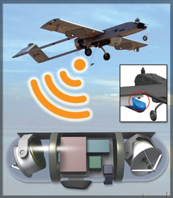
Figure 2 Airborne equipment description.
Essentially all of the Mobile Hotspot’s equipment in the L-3 design will be packaged into two underwing pods with the discovery and LTE antennas located at the wingtips and in the tail sections for isolation and spatial performance. Each pod contains several RF subsystems. Each pod contains two gimbaled mmWave radios, fore and aft; GPS antennas and IMUs; as well as associated power supplies. A total of four mmWave radios will provide the gigabit directional links with as wide an operating field-of-view (FOV) as possible. The remaining functions are split between pods, the primary network router in one and the discovery and LTE subsystems in the other – resulting in a good balance of weight and power between the two pods. Nominally, the mass of each pod is about 10 to 12 kg and each requires about 200 to 500 W depending on the operating mode. The size limitation of the pods is well established and realization is expected to be relatively low risk. Continued effort remains to contain the weight and power and drive the overall SWAP performance to provide operating margin to the Shadow.
In addition to the airborne equipment, there will be stationary ground-based nodes both mobile and compact deployable, as well as portable commercial LTE devices. The ground based nodes will be fully functional gigabit nodes similar in content to the pods but also providing access in and out of the network.
Networking Overview
Industry has invested significant resources in developing methods of creating networks and ways to get data to its intended destinations. These methods have been proven to be effective and reliable. However, traditional approaches assume links that are highly reliable and topologies that are relatively stable, such as fiber optic based connections. When attempting to apply these standard approaches to a wireless ad hoc airborne and ground-based backbone network, the links are not as reliable as wired solutions, and the topology is continuously changing – producing less than desirable results. A goal of the program is to add wedge solutions to industry standard networking protocol stacks to overcome these shortcomings and add additional features to account for the requirements of military users.
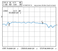
Figure 3 Millitech back-to-back WR-12 combiner loss.
This challenging scenario requires development and implementation of many features and capabilities not only at the link level but with regard to routing and provisioning as well. These include methods of: correcting bit errors and accounting for missed packets before higher layer protocols become aware of them; allowing routes to change quickly and often in order for data packets to efficiently reach their destination; and tolerating and accounting for constantly changing links. Since the gigabit backbone depends on directional links that have limited angles of regard, where these directional links should be pointed and when they might be reaching limits of field of regard and range also needs to be managed. Optimizing how nodes are connected in order to make data transfers efficient and minimize hops, managing data flows to ensure the optimal performance to users and perhaps most importantly, supporting data from and to outside ports are all essential tools for success.
Implementation of Mobile Hotspots is a marvel when these demands on the management of the backbone network are fully appreciated, further recognizing that the network is autonomous and self-forming as new nodes are deployed or replaced. The ability to then tie in and extend the network with LTE will enable multiple “Hotspots” over 1,000 square miles of area to be connected within hours. For the user, these features create a virtual network with high availability that provides a broadband Internet-like experience, leveraging the millimeter-wave gigabit links as the core transport mechanism.
Pointing, Acquisition & Tracking (PAT)
The ability to maintain highly directional mmWave links is the key to the success of the system. These paths must be reliable and stable to support gigabit links via antenna gains of nominally 40 dB and corresponding beamwidths of ~2 degrees. Supporting subsystems including the GPS/IMU and discovery radios contribute to achieving successful open loop link acquisition however, closed loop tracking is necessary to maintain robust links of this mobile environment. Each antenna is provisioned with tracking features to enable closed loop control.
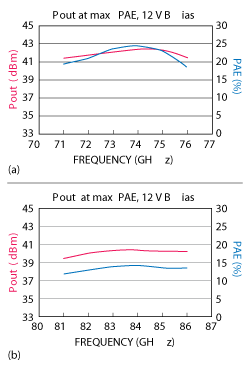
Figure 4 Power amplifier results from Phase 1, lower E-Band (a) and upper E-Band (b).
mmWave Radios
The mmWave radios require state of the art performance to enable the envisioned capacity and range. Performance is dominated by the basic link budget elements: transmit power, receiver noise figure, data rate (bandwidth & SNR) and antenna gain. Millitech demonstrated under Phase 1 amplifier module output power and amplifier module noise figure performance values that are now the baseline going forward.
The original objective of the power amplifier was to demonstrate 10 W (20 W goal) in each of the two E-Band allocations, 71 to 76 and 81 to 86 GHz. Millitech proposed use of HRL’s then in-process second generation GaN MMICs allowing for the potential to incorporate any suitable device should the opportunity arise. The approach was to design an integrated, highly efficient power combining scheme which we had been refined from spaceborne applications over recent years. Millitech had already demonstrated 0.7 dB of total loss divide and combined for an eight-way or 0.35 dB of combining loss (92 percent efficiency) Measured results are shown in Figure 3.
The final results of this Phase 1 activity resulted in the power amplifier performance exceeding the requirement for both the lower and upper allocation and approaching the 20 W goal by delivering 17 W at 74 GHz with nearly 25 percent PAE (see Figure 4). Note that the PAE figures include DC bias distribution. In addition to power and efficiency, size was another critical SWAP parameter. Each complete SSPA module was about the size of an iPhone with dimensions of 2.2" × 3.7" × 0.5" overall (<4.0 in3) (see Figure 5).
As part of Phase 1, BAE implemented their 50 nm mHEMT process in the design of a single LNA to cover both of the E-Band allocations. Millitech was enlisted by BAE to demonstrate the mounted-in-module performance. The results exceeded expectations, demonstrating the best seen MMIC based noise figures across very wide bandwidths. Nominally 2 dB noise figure was measured in each allocation at room temperature. A very flat gain response was measured to be below 2 dB in the 71 to 76 GHz allocation (see Figure 6). Worth noting is that the noise figure and gain behaved well and were maintained down to 40 GHz.
These accomplishments represent new industry performance benchmarks for solid state power capability and noise figure. Millitech looks forward to repeating and even enhancing this performance during phase 2. This work in mmWave performance, fostered by DARPA, will also provide substantial benefit to commercial mmWave communications.
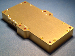
Figure 5 E-Band PA module from Phase 1.
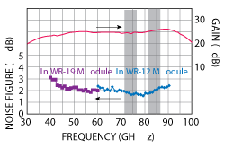
Figure 6 WR-12 LNA module results using mHEMT LNA.
Antenna Design
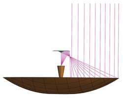
Figure 7 ADE ray trace.
The antenna gain is the remaining millimeter-wave performance element to highlight. Given the effort put forth to achieve the power and noise figure capability described, it stands to reason that a conventionally efficient antenna would undermine the effort. A conventional Cassegrain topology and even low or no blockage apertures with Gaussian illumination would typically struggle to achieve 50 percent efficiency across the frequency of operation for Mobile Hotspots, particularly when the aperture size is less than 50λ.
The overlying challenge of fitting within the pod structure, further constrained by the swept volume of the gimbal for steering; maintaining low mass to reduce the burden of the steering mechanisms while maximizing the aperture size and efficiency resulted in Millitech and L-3 selecting a shaped optics reflector topology. Similar to a Cassegrain in appearance, but with vastly different optics, as shown in Figure 7, it is commonly referred to as an Axial Displaced Ellipse (ADE). Through the use of today’s standard for modelling techniques, Millitech is modelling 65 percent aperture efficiency relative to the diffraction limit for the antenna aperture including feed losses and all blockages which is consistent with results we have measured at other frequencies.
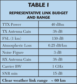
An ADE topology creates a focal ring in lieu of a typical focal point. The result is the peak illumination in a ring outside of the sub-reflector and very low illumination to the blocked areas. Additional losses of the polarizer and tracking features are minimized to less than 1 dB. Compiling an arbitrary link budget for the nominal performance benchmarks, it shows that in clear weather an air-to-air link can be made across 60 km as shown in Table 1. A 60 km node separation is an indication of the scale of area coverage attainable by Mobile Hotspots.
Future Developments
There are other technology advancements being pursued by industry. Advances in SiGe and CMOS are being made at a great pace and the technology was successfully utilized for Phase 1 of the Mobile Hotspots. In time, most of the millimeter-wave and modem functionality is likely to be replaced by a few highly integrated, low cost chips. It is also likely that the power and low noise standards established by GaN and mHEMT technologies will prove dominant for several years to come.
While the ongoing technology advancement at E-Band was instrumental in Mobile Hotpots, the program will continue to advance the performance standards which will no doubt have a direct effect on the future capability of commercial E-Band telecom products and other millimeter-wave applications as well. It is very possible that a Mobile Hotpots like system will soon be available for disaster recovery or even large scale cultural events where the existing infrastructure may be in need of added capacity.
Acknowledgment
The author extends his gratitude and acknowledgment to the entire Mobile Hotpots team with particular thanks to Dr. Richard Ridgway, DARPA program manager, and the Millitech team whose dedication and expertise has made these millimeter-wave results possible. DARPA approved for public release, distribution unlimited.