
In this article, the development of low cost, miniature, four-way RF transceivers in Ku-Band for MIMO wireless communication systems is presented. The RF transceiver operates with an FDD duplexing scheme, to obtain high bidirectional data throughputs and a simple network arrangement. The transceiver operates from 13.6 to 14.4 GHz, which is an experimental band for the next generation wireless communications in China. The RF bandwidth is up to 100 MHz, which makes it possible to support very high data rates (more than 1 Gbps). The whole four-way RF transceiver is fabricated on a single high-frequency multilayer PCB board, realizing a low cost transceiver with miniature size. A demonstration wireless communication system in Ku-Band has been successfully set up with the proposed RF transceivers.
Currently, wireless communication systems with over 1 Gbps data rates are of great interest in both research and industry areas. According to the definition of IMT-Advanced (4G) systems by the International Telecommunication Union (ITU), the next generation network should support approximately 1 Gbps data rates for low mobility. To meet this requirement, many advanced techniques, such as broad channel bandwidth, high-level modulation scheme (QPSK or higher level), orthogonal frequency division multiplexing (OFDM) and multiple-input multiple-output (MIMO) configurations, should be employed.1-3 Compared to a TDD communication system, an FDD scheme helps to obtain higher bidirectional data throughputs, simpler network arrangement for the RF transceiver and larger cell coverage, which is an attractive choice to support the high data rate communications.
However, the frequency arrangement for an FDD system is more difficult than for a TDD system. In order to support data rates up to 1 Gbps or more, the channel bandwidth will be at least 100 MHz.1 Thus, two continuous 100 MHz transmission bands are needed for a Tx and an Rx channel, respectively. A guard band of several hundred MHz, for Tx/Rx frequency separation, is necessary for feasible duplexer design with high isolation. The low RF frequency band (that is less than 6 GHz) is too crowded today to provide the required band resources. Besides, in a MIMO system, antenna elements are usually fed with uncorrelated signals and typically have a substantial spacing of at least half a wavelength from each other.4,5 This results in a bulky antenna array working with a low carrier frequency. More and more attention is focused on a higher RF frequency band of 6 to 15 GHz for future wireless communication systems.6 In this article, 13.6 to 14.4 GHz is the chosen RF frequency band for the transceiver, which is an experimental band for the next generation of wireless communications in China.

Figure 1 Ku-Band transceivers for MIMO base station and mobile terminal.
The transceiver in this article is developed for a 4×4 MIMO wireless communication system. After careful design and optimizations, a pair of low cost miniature four-way transceivers in Ku-Band is fabricated on a single PCB board. The RF performance of the transceiver is measured and provided in detail. In addition, a Ku-Band wireless communication demonstration system is set up successfully with the transceivers.

Figure 2 Conventional antenna arrangement (a) and filtenna arrangement (b) of the receivers.
Design and Implementation of a Four-way Transceiver in Ku-Band
Systematic Design
The block-diagram of the four-way transceivers in Ku-Band for the MIMO base station and MIMO mobile terminal are shown in Figure 1. For a MIMO communication system to work properly, the RF signal in each Tx/Rx channel has to be as uncorrelated as possible, which means the space between antenna elements (denoted as d1 the figure) should be large enough. Normally, in order to ensure uncorrelated fading characteristics of the wireless channel, the adjacent antenna elements should have a substantial spacing of at least a half wavelength,4,5 which is approximately 10 to 12 mm for a 13.5 to 14.5 GHz signal. The cable between the antenna and the RF transceiver will introduce a considerable insertion loss at Ku-Band, and thus degrade the overall performances of the transceiver. Here, the Tx/Rx antennas are directly connected to the RF ports with SMA connectors, avoiding the cable loss.

Figure 3 Schematic of one way in the transceiver.
In the design, d1 is equal to 110 mm (approximately 5 wavelengths of the carrier frequency), which makes the coupling between two adjacent antennas very weak. For FDD transceivers, the isolation between transmitting and receiving path is also very important. The relatively large d1 provides enough space to utilize two antennas for transmitting and receiving, respectively, instead of one in conventional FDD transceivers. Better isolation between the Tx and Rx paths can be reached with two filtennas,7 as shown in Figure 2. The conventional duplexer is no longer needed. The distance between the Tx and Rx antennas for one way in the transceiver, denoted as d2 in Figure 1, is equal to half d1 (that is 55 mm, or approximately 2.5 wavelengths at the carrier frequency), thus ensuring good balance between weak coupling and high isolation between Tx and Rx antennas.

The schematic of one way in the transceiver is shown in Figure 3. Table 1 gives the RF specifications. The classic super heterodyne architecture is utilized for this Ku-Band transceiver. A GaAs HEMT MGF4941AL is used for the low cost two-stage low noise amplifier (LNA) with ultra-low noise and reasonable gain to suppress the noise of the following stages. SIW image-rejection filters8,9 are employed for better performance than with the microstrip type. A high linear passive mixer is used, which demands +13 dBm LO pump power. FMM5061VF with 27 dB linear gain and +33 dBm P1dB power output is needed as the LO driver before the Wilkinson1-8 power splitter network. System-level simulation for one TRX way is performed with Agilent Advanced Design System (ADS) 2009. Table 1 also gives the system-level simulation results for the transceivers in MIMO base station and mobile terminal, respectively. The simulation result shows adequate margin, ensuring a promising measurement performance.
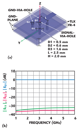
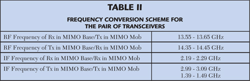
Figure 4 3D structure (a) and simulation results of the IF port configuration.

Figure 5 3D structure (a) and simulation results of the IF port configuration.
Implementation Considerations
Several methods are utilized to realize the low cost transceiver with miniature size. A high-frequency multilayer PCB board is used for the integration of the four-ways of the transceiver, the PLL module, LO power splitter network, power and control module, etc. The top-layer material is a Taconic TLX, with εr = 2.55 and a height of 0.508 mm. The other layers are all FR-4. In order to get rid of “metal jumpers” for crossing signal-transmission lines, a wide-band microstrip-to-microstrip via transition10 for the IF signal is used to get a simple circuit layout. IF signals (below 4 GHz) are transmitted from the top layer microstrip line to the bottom PCB layer through the signal-via-hole, as shown in Figure 4. Several GND-via-holes, acting as current return-path, are necessary for impedance matching. After design and simulation with Ansoft HFSS, excellent RF performance could be obtained with this transition. The simulation results show S11 and S22 below −30 dB and S21 above −0.1 dB from 1 to 6 GHz. Compared to low RF frequency transceiver, severe cross coupling is a critical issue in Ku-Band. Different function blocks, including passive/active RF blocks, DC power and control blocks, are separated by metal frameworks, in order to suppress cross coupling and shield interferences from other blocks and the environment. Figure 5 shows the pictures of the pair of four-way transceivers in Ku-Band.
Measurements and Results
Measured Performance of the Four-Way Transceiver in Ku-Band
Table 2 gives the detailed frequency conversion scheme for the pair of transceivers. The RF frequency is within 13.55 to 14.45 GHz. Brief measured results are given for key blocks of the transceiver in Table 3.
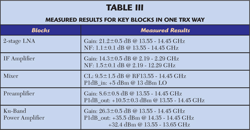
Figure 6 gives the measured return loss of the transceivers for the MIMO base station and MIMO mobile terminal. A low return loss is obtained at the RF ports of the transceivers, ensuring a good matching with antennas.
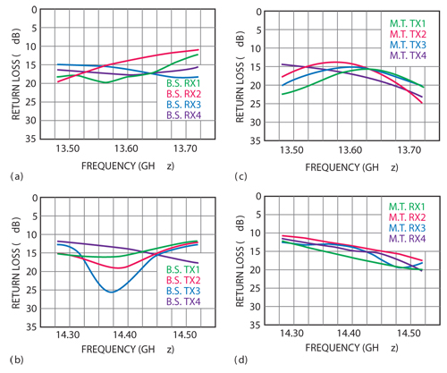
Figure 6 Measured return loss of RF ports for MIMO BS receiver (a), BS transmitter (b), MT transmitter (c) and MT receiver (d).
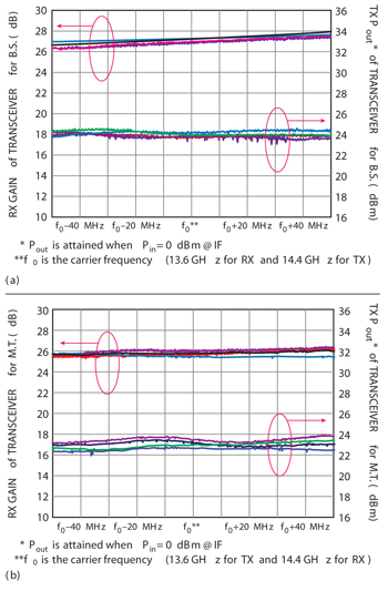
Figure 7 Rx gain and Tx output power of the four-channel transceivers for MIMO base station (a) and mobile terminal (b).
Figure 7 shows the measured Rx gain and Tx output power of the four-way transceivers. Cable insertion loss has been calibrated. Detailed comparison between the RF specifications, simulation and measured results are listed in Table 4.

Demonstration of a Ku-Band Wireless Communication System
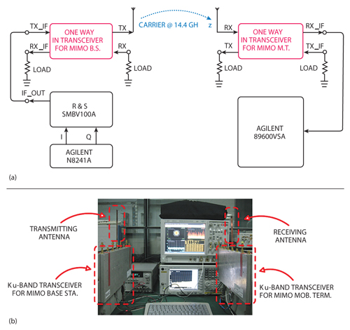
Figure 8 Schematic (a) and photograph of the wireless communication system under test (b).
Finally, to evaluate the overall performance, a Ku-Band wireless communication demonstration system is set up for error vector magnitude (EVM) measurement, with a pair of the proposed transceivers. Figure 8 gives the schematic and photograph of the wireless system under test. The desired IQ baseband signals are first generated with Agilent N8241A and then modulated with Rohde & Schwarz SMBV100A to output the IF signals. The transceiver for the MIMO base station up-converts the IF signal and then the transceiver for the MIMO mobile terminal down-converts the IF signal, which is demodulated and analyzed by Agilent 89600VSA for EVM.The carrier frequency is 14.4 GHz.
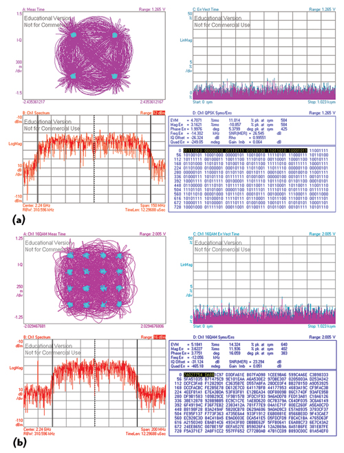
Figure 9 Ku-Band wireless communication system measured results for a 100 Ms/s QPSK signal (a) and a 100 Ms/s QAM signal (b).
For demonstration, the input power at the TX_IF port is set to −30 dBm, and the distance between Rx and Tx antennas is set to 0.80 m. Other unused RF and IF ports are all terminated with matching loads. In the measurement, the baseband signal with 100 M symbol/s under QPSK and 16QAM modulation is applied to the wireless system. The signal constellation and other results are depicted in Figure 9. The measured EVM is 4.7 percent rms and the SNR is 26.5 dB for a 100 M symbol/s QPSK signal; the measured EVM is 5.2 percent rms and the SNR is 23.2 dB for a 100 M symbol/s 16QAM signal.
Conclusion
In order to support very high data rates (more than 1 Gbps) and bandwidth of up to 100 MHz for next generation MIMO wireless communication system, a pair of four-way transceivers in Ku-Band, with an FDD scheme, have been developed. For highly integrated transceivers, a low-cost high-frequency multilayer PCB technique has been utilized during fabrication. The experimental results have proved the excellent RF performance of the transceivers. All of the measured results fully meet the design requirements. Finally, the overall performance of one complete RF channel is evaluated with a Ku-Band wireless communication system. Measured results show that the demonstrated Ku-Band wireless system successfully supported wireless communication in Ku-Band with 100 Ms/s QPSK and 100 Ms/s 16QAM signals with low EVM.
Acknowledgments
This work is supported in part by the NSFC under Grant 60921063 and in part by the National Science and Technology Major Project of China under Grants 2010ZX030007-02-01 and 2011ZX03004-003.
References
- Z.Q. Yu, J.Y. Zhou, J.N. Zhao, T. Zhao and W. Hong, “Design of a Broadband MIMO RF Transmitter for Next-generation Wireless Communication Systems,” Microwave Journal, Vol. 53, No. 11, November 2010, pp. 22-26.
- A.J. Paulraj, D.A. Gore, R.U. Nabar and H. Boelcskei, “An Overview of MIMO Communications—A Key to Gigabit Wireless,” Proceedings of the IEEE, Vol. 92, No. 2, February 2004, pp. 198-218.
- T. Kaiser, A. Wilzeck, M. Berentsen and M. Rupp, “Prototyping for MIMO Systems: An Overview,” 2004 European Signal Processing Conference Proceedings, pp. 681-688.
- M. Rumney, “The MIMO Antenna: Unseen, Unloved, Untested,” Microwave Journal, Vol. 53, No. 8, August 2010, pp. 22-34.
- A. Kalis, A.G. Kanatas and C.B. Papadias, “A Novel Approach to MIMO Transmission Using a Single RF Front End,” IEEE Transactions on Selected Areas in Communications, Vol. 26, No. 6, August 2008, pp. 972-980.