

In the development of next-generation radar and electronic warfare (EW) systems, typical test scenarios include simulations such as low-observable signals mixed with ground clutter and environmental interferers. Addressing these demanding scenarios requires an arbitrary waveform generator (AWG) or signal-scenario generator (SSG) that has two key attributes. The first is a design that provides wide bandwidth and high resolution simultaneously. The second is built-in capabilities that support the creation of long, complex signal scenarios.
The Agilent M8190A SSG is well equipped for these challenges. With 14-bit resolution at 8 GSa/s or 12-bit resolution at 12 GSa/s, the M8190A offers two modes that ensure excellent signal fidelity at high frequencies. It also enables long playback time with up to 2 GSa of waveform memory and a variety of advanced sequencing capabilities. For radar and EW system creators, these capabilities can lead to shorter development time and a lower cost of test.
Designing for Exceptional DAC Performance
Typical AWGs force system creators to make a tradeoff between units that offer either wide bandwidth and low resolution or limited bandwidth and high resolution. The respective levels of performance in both bandwidth and resolution depend on the digital-to-analog converter (DAC) used in the AWG. Bandwidth is limited by the DAC sample rate, and accuracy is affected by the quality and performance of the analog components used inside the device.

Figure 1 Resampling of the DAC output improves the quality of the final waveform.
Within Agilent, researchers at the company’s Measurement Research Lab have developed a way to eliminate the spurious signals (spurs) and distortion present in typical DAC designs. Agilent’s patented approach focuses on the beginning of the signal-generation process, reducing the need for filtering at the end of the signal chain. This approach is based on two key ideas. One is to let switched current sources settle within the DAC. The other is to resample the signal with a special low-noise clock before outputting the simulated signal (see Figure 1).
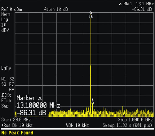
Figure 2 A single-tone output at 555 MHz (7.2 GHz sampling rate) had a SFDR of -86.31 dBc in the range to 1 GHz.
The resulting DAC output provides spurious-free dynamic range (SFDR) of up to 80 dBc, which is much better than what most other designs can achieve. At 8 GSa/s, the Agilent DAC typically delivers an industry-leading 75 dBc SFDR (excluding second and third harmonics) across an output frequency range of 0 to 3 GHz (see Figure 2).
One of the most important design choices was the decision to use a low-temperature, multi-layer ceramic substrate. A package with many layers is necessary in order to meet aggressive specifications for noise and spurious response. The net result is excellent performance at high frequencies. As implemented in the M8190A SSG, the ability to achieve high resolution at high frequency gives system developers greater confidence that they are testing their design, not the signal source.
Enabling Complex Signal Scenarios
To create realistic signal scenarios, an AWG or SSG needs more than raw DAC technology. Three additional attributes enable sufficiently long playback times: waveform memory, advanced sequencing capabilities and real-time access to individual memory segments.
The M8190A SSG can be configured with 128 MSa (standard) to 2 GSa (optional) of waveform memory per output channel. With 2 GSa installed, the maximum playback time of a single unique waveform is 180 ms at the highest sample rate.
The absolute amount of waveform memory is important; however, using the available memory efficiently enables a concept called memory gain. Typical AWGs consume valuable memory space by requiring multiple occurrences of identical segments that are repeated within a sequence. In the M8190A, advanced sequencing capabilities such as stepping, looping and conditional jumping make it possible to create such segments once and reuse them programmatically as needed. These capabilities can be applied to waveforms or waveform sequences.
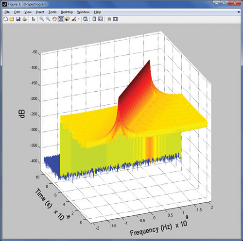
Figure 3 Spectrograph of a chirp that is part of a longer signal scenario.
Specific to the M8190A, up to 256,000 segments can be stored in memory, and up to four billion loops can be defined for each segment. Beyond the sequencing of individual segments, it is possible to set up a series of advanced sequences. This enables users to build and playback highly complex scenarios comprised of one or more sequences (see Figure 3).
The third attribute is a hardware-based dynamic sequence-control input. This eight-bit bus is used to enable immediate or synchronous switching between segments or sequences. Immediate jumps interrupt the active segment or sequence before completion; synchronous jumps wait until the active segment or sequence is completed. The actuating signals can come from the unit under test, another instrument within the system, or any other external device.
Creating Signals in Software
Software is a fourth element in the solution set. Examples include Signal Studio from Agilent, MATLAB from The MathWorks and LabVIEW from National Instruments. These provide an environment for signal creation, and the results can be downloaded to the SSG memory for playback.

Figure 4 Pulse Builder enables creation of sophisticated singleemitter test patterns.
Two versions of Signal Studio are especially relevant in aerospace and defense applications. Signal Studio for Pulse Building (N7620A) simplifies the creation of complex pulse patterns for the testing of radar receivers (see Figure 4). Signal Studio for Multitone Distortion (N7621A and N7621B) can be used to create multi-tone and noise power ratio signals for the testing of satellite transceivers.
Another useful application is Agilent SystemVue electronic system-level (ESL) design software. The Radar Model Library for SystemVue (W1905) includes predefined radar signals that can be selected and loaded into the M8190A, for example. The library also provides more than 35 highly parameterized primitive blocks and higher-level reference designs that can be used to create a working radar system. The block set and its example workspaces serve as algorithmic and architectural reference scenarios to verify radar performance with a variety of signal conditions: target and radar cross section (RCS) scenarios; clutter conditions; jammers and environmental interferers; and different receiver algorithms.
Conclusion
Advanced AWGs and SSGs provide important benefits in the development of present and future radar and EW systems. The greatest technical advantage is the possibility of creating simulated signal scenarios with enhanced realism. This helps minimize the need for costly flight testing and enhances the flexibility of ground-based testing.
From a business perspective, greater flexibility makes it possible to test multiple radar or EW designs with a single measurement system, enhancing system reuse. Further, modules such as the M8190A are based on commercial off-the-shelf (COTS) technology such as AXIe. A modular approach helps reduce the size, weight and physical footprint of the test system.
Agilent Technologies Inc.,
Santa Clara, CA
(800) 829-4444
www.agilent.com