
Microwave printed antenna arrays (PAA) have various advantages over conventional antenna systems, due to their low cost, great reproducibility and the possibility of integration with other microwave circuits. Because of this, they are often used in telecommunication systems, such as indoor and outdoor wireless LANs, point-to-point and point-to-multipoint, and also in radar microwave and millimeter-wave systems. One of the main antenna characteristics is SLS in radiation patterns, which is defined for telecommunication systems (usually for microwave links) by international standards and recommendations.1 Also, in conventional radar systems, the SLS requirements are much more severe since responses from side lobes are practically false targets. Depending on the antenna class, the desired SLS in telecommunication systems is approximately 20 to 40 dB; in radar systems the required suppression is even higher. Such SLSs are hardly achievable with conventional microstrip antenna arrays (with patches). In conventional microstrip PAAs presented in the literature, side lobe levels are at best suppressed by 25 dB (related to the main lobe). A relatively small number of publications dealing with this issue are available.2-4
The main characteristics of conventional PAAs with patches, which prevent obtaining high SLSs, are the following: great influence of the patches dimensions tolerances on the real and imaginary part of their impedances; mutual coupling between radiating elements; limitations in the feasibility of feed network realization; and surface wave effects as well as parasitic radiation from the feed network. This article introduces solutions that overcome or considerably diminish practically all these limiting factors. The proposed antenna structure is suitable for integration with other passive or active microwave circuits on a common dielectric substrate.
Relevant Limiting Factors in the Realization of PAAs with High SLS
The great influence of patches dimensional tolerances on the possibility of realizing antenna arrays with high SLS is the consequence of their rapid impedance variation with dimensional changes that may occur during fabrication or with temperature change. A similar conclusion relates also to a feed network—phase and amplitude deviations appear due to tolerances of feeding lines dimensions (lengths and widths) as well as of impedance transformers, which enable tapered distribution—resulting in high SLS.
Figure 1 Pentagonal dipole as a basic element of the antenna array printed on a dielectric substrate.
Pentagonal Dipole Fed by a Symmetrical Microstrip Line
Besides conventional printed antenna arrays with patches fed by a conventional nonsymmetrical microstrip line, there are printed antenna arrays with printed dipoles usually of pentagonal shape (one half of them on one side and another half on the opposite side of the substrate). These dipoles operate at their second resonance and are fed by a symmetrical (balanced) microstrip line,5-7 as shown in Figure 1.
By using the proposed radiating elements, a phase change of approximately 12.5° for a frequency variation of 30 percent was obtained, which is approximately 30 times greater than in the case with patch antennas.2 The magnitude variation in the same frequency range is only 2 dB. Also, due to the fact that the feed network is symmetrical and consists of symmetrical (balanced) microstrip lines, the parasitic radiation from it, as well as the surface wave effect, are practically eliminated. The majority of the factors that make difficult the realization of printed antenna arrays with high SLS has been eliminated by using the proposed radiating elements.
Figure 2 Sketch of the axial pentagonal dipole array in the corner reflector.
Tapered Distribution
In order to decrease the side lobe levels, various tapered distributions are used in antenna arrays: cosine, cosine-squared, Gaussian, Taylor, Dolph-Chebyshev, etc. These distributions are chosen depending on the required side lobe attenuation, possible pedestal in distribution (Imax/Imin ratio), desired position of the radiating elements, desired position, that is distribution of side lobes, distance between radiating elements, number of radiating elements and expected tolerances in fabrication.
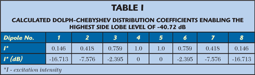
An axial array of eight printed pentagonal dipoles, operating at their second resonance and with mutual distance of 0.85λ0, are investigated and shown in Figure 2. The dipoles are fed by a feed network enabling Dolph-Chebyshev distribution of the second order with pedestal (Imax/Imin) of 17 dB.8 Under these conditions, the distribution coefficients shown in Table 1 have been obtained, which enable the highest side lobe level of -40.72 dB in the ideal case.
Error Influence on Degradation of SLS
Due to tolerances in the photolithographic process, as well as to dimensional changes caused by temperature variation, deviations from projected values of position, amplitude and phase of radiating elements in the array occur. The influence of these tolerances has been investigated in the case of a printed antenna array with eight axially placed broadband pentagonal dipoles operating at their second resonance. Expected tolerances in standard photolithographic process have been assumed with moderate precision, in order to estimate the SLS degradation, due to amplitude and phase deviations as well as radiating elements positioning deviations from optimized values.
Realizable values of relative tolerances have been assumed at the operating frequency of 26 GHz:
- deviations in distances between radiating elements in the array: 1 or 2 percent of λ0 (corresponding to approximately 115 or 230 μm)
- phase deviations: 2° or 4° (corresponding to approximately 40 or 80 μm tolerances in the length of the feeding line)
- amplitude deviations along tapered feeding lines: 1 or 2 dB (occurring as a consequence of tolerances in transformer lines widths and lengths)
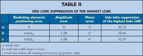
Using a previously published method,8 the SLS has been calculated for the Dolph-Chebyshev distribution of the second order with pedestal (Imax/Imin) of 17 dB for the array with eight axially placed dipoles (the distance between dipoles was 0.85λ0). The results are presented in Table 2. The errors were randomly distributed in the simulation process (Monte-Carlo method).

Figure 3 Simulated E-plane radiation patterns.
Figure 3 shows the simulated E-plane radiation patterns for the cases given in Table 2. The blue trace is the ideal case, while the red and green traces are for the two real cases (with minor and greater amplitude, phase and radiating elements positioning deviations, respectively). The results of tolerance simulation (performed at 26 GHz) of particular factors that degrade SLS of the proposed PAA show that the expected SLS is 35.04 dB (in the case of minor errors) and 32.15 dB (in the case of greater errors in the standard photolithographic process).
Concept and Design of the Linear PAA with a Corner Reflector
The proposed antenna array consists of three parts: (1) an axial array of eight printed pentagonal dipoles; (2) a feeding network and a balun printed on the same dielectric substrate as the pentagonal dipoles; (3) and a corner reflector consisting of two metal plates with the aperture angle α = 45°. The distance between the dipoles (at the center frequency) is chosen in such a way as to obtain a relatively high array gain with sufficient SLS in the tapered array. In the present case, the distance between the axial dipoles is 0.85λ0. Also, with such a distance between axial dipoles, the mutual coupling is very low, which makes the design and optimization of the antenna array relatively easy.

Figure 4 Simulated real and imaginary parts of the dipole's impedance vs. frequency (α = 45°).
The dipoles and the feed network are fabricated on the same dielectric substrate with εr = 2.1, thickness h = 0.254 mm and dissipation factor tan δ = 4 10-4. The dimensions of a single radiating element (printed pentagonal dipole) placed in a corner reflector are optimized as to obtain an impedance Z ≈ 100 Ω. The corner reflector plate's length is L = 4λ0, while the dipole distance from the apex (S) is 0.7λ0. The optimized impedance obtained at 26 GHz is (98.6 - j6.5) Ω.The simulated real and imaginary parts of the single dipole's impedance versus frequency are shown in Figure 4.
The simulated VSWR is less than 2 in the frequency range from 24 to 33 GHz. Then the array, consisting of four identical axially placed pentagonal dipoles with dimensions obtained in the optimization of a single dipole, was modeled. The distance between dipoles was 0.85λ0. Due to mutual impedances, deviated impedances values: Z1 = Z4 = (84.4 - j24.3) Ω and Z2 = Z3 = (70.3 - j26.5) Ω. Since the values obtained differed slightly from the ideal ones, as well as the optimization process with a greater number of dipoles (together with a reflector) would require great computational capacity, in the next step, an array consisting of eight dipoles with the same dimensions as in the case with four dipoles was analyzed; impedances: Z1 = Z8 = (82.6 -j18.0) Ω, Z2 = Z7 = (70.7 - j18.0) Ω, Z3 = Z6 = (70.6 - j19.8) Ω, Z4 = Z5 = (71 -j16.6) Ω were obtained. The software package WIPL-D9 has been used in these analyses.
Figure 5 Layout of one half of the tapered feed network of the 26 GHz array.
Feed Network and its Component Parts with Impedance Transformers
In order to attain the desired distribution (see Table 1), the feed network was designed using a symmetrical (balanced) microstrip technique with λ/4 transformers, assuming 100 Ω impedances at its ends. The corresponding layout is shown in Figure 5. Characteristics and dimensions of the λ/4 transformers with symmetrical microstrip lines have been calculated using TEM analysis.
The feed network was loaded with the impedances obtained in the previous step of the analysis (Z1,…, Z8). Since certain deviations from the ideal required network were observed, corrections of phase deviations were accomplished by changing the lengths of particular branches in the feed network using the program package IE3D10 in order to achieve an in-phase network.
Realization of Printed Tapered Antenna Array with a Corner Reflector
The corner reflector is designed using results from an A.C. Wilson published article,11 which contains very detailed experimental results obtained by variation of length (L), width (W), aperture angle between corner reflector plates (α) and distance of radiating element from apex (S). A suitable radiation pattern with relatively high SLS in the Hplane is obtained with L = W = 4λ0, α = 45° and S = 0.7λ0.
Figure 6 Normalized simulated E-plane pattern at 24, 26 and 28 GHz.
The axial array with feed network and balun12 is placed between two metallic plates forming a corner reflector with α = 45°. The beamwidth in the H-plane (azimuth) depends mainly on the angle between the metallic plates and the length of the reflector plates (L), while the SLS in the E-plane depends only on the PAA. The feeding lines for the dipoles penetrate the junction of the two reflector plates. At the junction there are holes through which symmetrical microstrip lines of the feeding network pass. The influence of the metallic plate on the microstrip lines is minimized by selecting a sufficient diameter (2 mm) for the holes.
Figure 7 Simulated and measured radiation patterns in the E- and H-planes at 26 GHz.

Figure 8 Measured return loss of the antenna array.
Results and Comments
The simulated and measured results are shown in Figures 6 to 8. The discrepancy between simulated and measured SLS is due to tolerances in photolithography and mounting process because relatively small inaccuracies can significantly influence the precise distribution, which corresponds to simulations given in Table 2. The measured highest SLS in the E-plane is 34.7 dB (see Table 3) showing excellent agreement with the result of tolerances influence simulation (35.4 dB; see Table 3).

The return loss measured at the SMA connector is shown in Figure 8. The measured gain of the antenna is approximately 1 dB lower than the simulated one because the feed network, balun and transition from microstrip to SMA connector were not taken into account. A photograph of the fabricated PAA with tapered distribution and a 45° corner reflector operating in the 26 GHz range is shown in Figure 9, compared to a US quarter. The most significant achievement is the high SLS in the E-plane, since it depends only on the PAA.

Figure 9 Photograph of the fabricated antenna array with corner reflector.
Conclusion
Conventional antenna arrays, with patches used as radiating elements, have relatively low suppression of side lobes, and thus do not satisfy the standards and recommendations for most telecommunication and radar systems. The several limiting factors in the realization of printed antenna arrays with relatively high SLS are investigated and simulated: phase deviations, amplitude deviations, radiating elements positioning deviations, mutual coupling between elements and parasitic radiation from the feed network.
The characteristics of the linear antenna array, consisting of axially placed pentagonal dipoles operating on the second resonance and fed by a symmetrical (balanced) microstrip line, are analyzed. The analysis has shown that tolerance sensitivity of the investigated array (real and imaginary part of dipoles' impedances variation, which is one of the main limiting factors in the realization of printed arrays with high SLS) is about 30 times less in comparison with conventional antenna arrays with patches. An antenna structure, with printed pentagonal dipoles forming the array, is proposed. The dipoles operate at their second resonance and are fed by symmetrical (balanced) microstrip lines. An array, consisting of eight axially placed dipoles, is fed through the feed network with impedance transformers, enabling Dolph-Chebyshev distribution of the second order with pedestal Imax/Imin = 17 dB. The corner reflector, in which the linear antenna array is placed, achieves a relatively high SLS and narrow beamwidth even in the H-plane. The effects of particular parameters, with assumed tolerances on which SLS depends, have been analyzed.
The measured beamwidth in the E-plane at 26 GHz is 10.7°. The experimentally obtained E-plane SLS at 26 GHz, which depends only on the antenna array, is better than 34 dB and is, to the authors' knowledge, the best result published to date. The measured |S11| is better than 10 dB (VSWR<2) in the range from 22 to nearly 30 GHz. The array is realized using a standard photolithographic process, with a moderate precision of ±10 μm. The simulated and measured results are in very good accordance. The antenna structure shown is suitable for integration with other passive and active microwave circuits on a common dielectric substrate and can also be used in higher millimeter-wave ranges up to 110 GHz.
Acknowledgment
The authors would like to thank Milka Marjanovic and Momcilo Tasic for their contribution to the fabrication of the antenna model. This work has been supported by the Serbian Ministry of Science and Technological Development.
References
- IEEE Standard for Local and Metropolitan Area Networks (System Profiles for 10-66 GHz), IEEE, 3 Park Avenue, New York, NY, 15 January 2003
- D.M. Pozar and B. Kaufman, "Design Considerations for Low Sidelobe Microstrip Arrays," IEEE Transactions on Antennas and Propagation, Vol. 38, No. 8, August 1990, pp. 1176-1185.
- J. Hirokawa and M. Ando, "Sidelobe Suppression in 76 GHz Post-wall Waveguide-fed Parallel Plate Slot Arrays," IEEE Transactions on Antenna and Propagation, Vol. 48, No. 11, November 2000, pp. 1727-1732.
- Yuichi Kimura, et al., "76 GHz Alternating-phase Fed Single-layer Slotted Waveguide Arrays with Suppressed Sidelobes in the E-plane," 2003 IEEE AP-S International Symposium Digest, Vol. 3, pp. 1042-1045.
- A. Nešić, D. Nešić, V. Brankovic, K. Sasaki and K. Kawasaki, "Antenna Solution for Future Communication Devices in mm-Wave Range," Microwave Review, Yugoslav IEEE MTT-S Chapter, Vol. 7, No. 3, December 2001, pp. 9-17.
- A. Nešić, V. Brankovic and I. Radnović, "New Generation of Millimeter-wave Communication Systems," Microwave Review, Yugoslav IEEE MTT-S Chapter, Vol. 6, No. 1, December 1999, pp. 13-18.
- A. Nešić, Z. Mićić, S. Jovanović, I. Radnović and D. Nešić, "Millimeter-wave Printed Antenna Arrays for Covering Various Sector Widths," IEEE Antennas and Propagation Magazine, Vol. 49, No. 1, February 2007, pp. 113-118.
- M. Mikavica and A. Nešić, CAD for Linear and Planar Antenna Array of Various Radiating Elements, Artech House Inc., Norwood, MA, 1992.
- B. Kolundzija, J. Ognjanovic and T.K. Sarkar, WIPL-D Pro v5.1.
- Zeland Software Inc., IE3D User's Manual.
- A.C. Wilson and H.V. Cottony, "Radiation Pattern of Finite-size Corner-reflector Antennas," IRE Transaction on Antennas Propagation, Vol. 8, No. 2, March 1960, pp. 144-157.
- A. Nešić and S. Dragas, "Frequency Scanning Printed Array Antenna," 1995 IEEE AP-S International Symposium Digest, pp. 950-953.
- A. Nešić, I. Radnović and M. Šunjevarić, "Transmitter Front-end for Millimeter-wave Link Operating at 60 GHz Range," 17th Telecommunications Forum TELFOR 2009, November 2009, Belgrade, Serbia.
- A. Neöic¥,, I. Radnovic¥ and M. äunjevaric¥, "Receiver Front-end for Millimeter-wave Link Operating at 60 GHz Range," 17th Telecommunications Forum TELFOR 2009, November 2009, Belgrade, Serbia.
Aleksandar Nešić received his MSc and DSc degrees and the title of full professor in electrical engineering from the University of Belgrade, Yugoslavia, in 1982, 1984 and 1995, respectively. He became scientific advisor at the Institute of Applied Physics-Belgrade in 1985. He is currently Research Director of the Institute for Microwave Techniques and Electronics, Belgrade.
Ivana Radnović received her BS degree in electrical engineering from the School of Electrical Engineering, Belgrade University, in 1987. Since 1987, she has been with the IMTEL Institute, Belgrade, Serbia, as a Research and Design Engineer. She is currently working toward her PhD degree. Her current research interests include the analysis and design of microwave and millimeter-wave printed antenna structures.
Zoran Mićić received his Diploma Engineer degree in electrical engineering from the School of Electrical Engineering, Belgrade University, in 2001. He is currently working toward his PhD degree. Since 2001 he has been with the IMTEL Institute, Belgrade, Serbia, as a Senior Project Engineer. His research interests include microwave parabolic and microstrip antennas.
Sinisa Jovanović received his Diploma Engineer degree in electrical engineering from the School of Electrical Engineering, Belgrade University, in 1987. He is currently working toward his PhD degree. From 1987 to 1998 and from 2003 to present he has been with the IMTEL Institute, Belgrade, Serbia, as a Senior Project Engineer for the microwave section of radio-relay links. From 1998 to 2002 he was with Philips Broadband Networks and C-Cor.net, Manlius, NY, as a design and system engineer for CATV amplifier development. His current research interests include microwave amplifiers, subharmonic mixers as well as printed filters and antennas.