
Electromagnetic (EM) simulation provides accuracy at the expense of speed. In situations where accuracy is crucial and the problem size large, such as compacting an RFIC or complex RF board onto a small area to meet cost and size requirements, simulation times can be unbearably long. When each simulation takes more than a day to complete, the designer’s patience and desire to use EM analysis soon runs out. This is why EM is often used as a last resort or as a one-time, sign-off verification tool rather than the accurate, interactive design tool that it can be.
Transforming EM from a verification to a design tool is the focus of the latest release of Momentum, the 3D planar EM simulator from Agilent EEsof EDA. Innovations that include algorithmic improvements in meshing and solving, together with computing usage of multi-core threading and multi-computer parallelism, give at least a 10x improvement in simulation speed with greatly reduced memory usage. This enables large problems to be solved accurately in hours instead of days. The improved Momentum simulator is part of the Advanced Design System (ADS) 2008 and RF Design Environment (RFDE) Update 1 release.
Momentum Technology Improvements
The 10x speed improvement is generated through a combination of new features, including:
• A layout pre-processor to remove layout inconsistencies.
• A new, multi-level compression matrix solver for faster loading and convergence.
• Multi-threaded simulations on single multi-core machines for fast parallel Momentum simulations.
• Distributed simulations on computer clusters for additional speed and performance improvements.
Layout Pre-processor
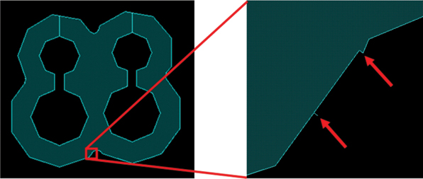
Momentum works at the physical design level and therefore needs a layout from which to start its computations. The principles that guide mask generation from layout information are not the best for simulation. Masks contain overlaps and long and narrow wedges that can lead to ill-defined mesh elements and ultimately to a lack of simulation convergence. Momentum now contains a layout pre-processor that removes visible and invisible layout resolution problems prior to meshing (see Figure 1).
Multi-level Compressed Matrix Solver
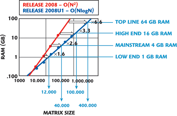
More complex problems solve much faster with Momentum’s new matrix solver, as shown in Figure 2. The order reduction of the momentum solver enables a faster direct solver method that uses less memory. The new direct solver algorithm brings problems that once took a day to solve to below an hour of simulation time through improved convergence and load times.
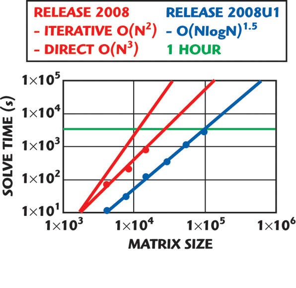
Figure 3 shows how the different solvers have increased simulation speeds. The classic direct LU factorization solver simulation time grows at the rate of O(N3) while an iterative solver reduces it to O(N2), where N is the number of unknowns representing the problem size. The latest multi-level compressed matrix direct solver reduces simulation times further to grow at only O(NLogN)1.5.
Multi-threaded Simulations on Single Multi-core Computers
Modern-day computers have dual cores as a standard feature. Optimal use of the available cores on today’s computers help to parallelize Momentum simulations.
Figure 4 compares the S11 simulation results of a 16-element array of a multilayer-aperture-coupled antenna. The simulations show a 3x simulation speed-up and a 40 percent memory reduction.

Distributed Simulation
With Momentum’s distributed simulation feature, designers can spin off a simulation to a different machine in a computer cluster for every frequency point in the simulation. Multi-grid structures can make use of their full capacity to speed up simulation; multi-threaded simulation processes running on separate computers will yield additional speed.
Example: Power Amplifier Design and Optimization for a WLAN 802.11b Transceiver
Silicon power amplifier design has thus far been the realm of synthesis tools that allow generation of spiral inductor models and RF interconnects, but perform poorly in providing true, whole-chip EM optimization and verification. The new Momentum engine provides full planar 3D simulation of the inductors of the power amplifier in less than a minute, making optimization practical. The die size was reduced by over 32 percent through planar EM simulation of an existing power amplifier, directly impacting chip performance and costs.
The power amplifier shown in Figure 5 has 11 coupled inductors, the effects of which need to be taken into account along with the electrical behavior of the circuit. The design and simulation flow consists of the following steps:
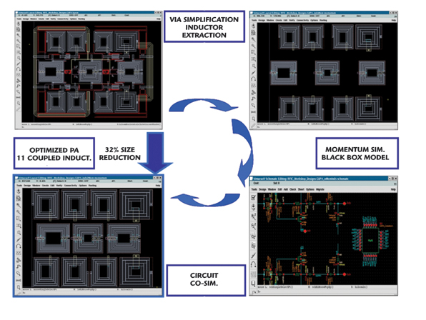
1. A via simplification algorithm to remove irrelevant vias.
2. An inductor extraction process.
3. The Momentum simulation of the 11 coupled inductors leading to the black-box generation using S-parameters.
4. The black-box circuit co-simulation.
A power gain compression and power-added efficiency simulation of the power amplifier was then performed, while optimizing the structure to occupy a minimal footprint.

Table 1 shows an analysis of the effects of placing the spiral inductor on the power amplifier. The table shows that the power amplifier footprint was reduced by 32 percent. Follow-on optimization runs can take the amplifier specifications into account.
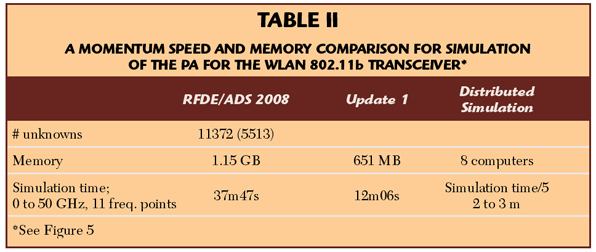
With Momentum for RFDE/ADS 2006A, a machine with 2 GB of RAM was unable to simulate all 11 spirals together, because the simulation ran out of memory. Instead, the four bias spirals were simulated together and the three spirals in the signal path were simulated individually. With the new Momentum release, all 11 of the spirals can be simulated together using about 1.2 GB of RAM and taking 38 minutes on the same machine. Today’s Momentum cuts the problem size in half and triples the simulation speed using the multi-level compressed matrix solver, as shown in Table 2.
Signal Integrity Verification
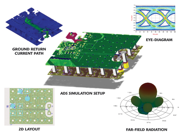
Another excellent application for the new Momentum simulator is for signal integrity verification of high-speed digital designs. Figure 6 shows an example of a multi-gigabit PCB board for a high speed serializer/deserializer (SERDES) chip where the serial link between the chip and board interconnect must preserve signal integrity for optimal BER and eye diagram opening. For signal integrity verification, structures of several wavelengths quickly become challenging: For accurate simulation, at least eight frequency points per turn on the Smith chart need to be considered.
This previously unsolvable structure with 30,000 unknowns in earlier Momentum versions can now be solved for 77 frequency points in under two hours, with 1.7 GB of memory on a quad-core machine. Parallelizing the simulation on n number of machines can yield another (n–2)x of speed-up.
Conclusion
RFIC designers can now use full EM simulation in their design work, and not just as a verification tool. Simulations that took days to finish and were used only to verify the final design can now be run in minutes, bringing design and optimization well within reach. In addition, structures that can be verified for signal integrity problems with Momentum are limited only by the number of parallel computers in the distributed network.
To learn more about Agilent’s Momentum planer EM simulator, visit www.agilent.com/find/eesof-momentum. For more information about all of Agilent’s EEsof EDA solutions, visit www.agilent.com/find/eesof.
Agilent Technologies Inc.
Santa Clara, CA
(800) 829-4444
RS No. 300