
The hybrid ring has been widely used in microwave systems, due to its simplicity and performance. Because of the long electrical length of the ring itself, size reduction is becoming a major design consideration for many practical applications. Furthermore, when designing a microwave system, how to effectively handle the harmonic signals from nonlinear devices is one of the decisive factors for system performance. For these reasons, many attempts to reduce the size and/or harmonics of the hybrid ring have been reported.1–6,8
To simultaneously achieve a significant size reduction and harmonic suppression, a low pass unit cell (LUC) was proposed to design the hybrid ring.4,5 The hybrid was one fourth of the conventional one in size, and the third harmonics are suppressed by approximately 20 dB.
However, due to the complicated LUC structure, close attention had to be paid to the LUC’s arrangement, which includes the bending of six open stubs and considering the parasitic effects from the complexity in designing the ring hybrid. In this article, to solve the problem and reduce additional harmonics, a new miniaturized ring hybrid is proposed, in which an LUC is used, simply composed of a parallel-coupled line of the hairpin-type and two short transmission lines.
Design
The prototype of the hairpin-type coupled line was used to design a compact low pass filter with a wide stopband.7 It is possible to create its equivalent circuit to be a λ/4 transmission line, maintaining the low pass filter (LPF) characteristic, by adjusting the dimensions. This LUC is superior to the previously reported LUC in the simplicity of its structure and its ability to suppress the harmonics.
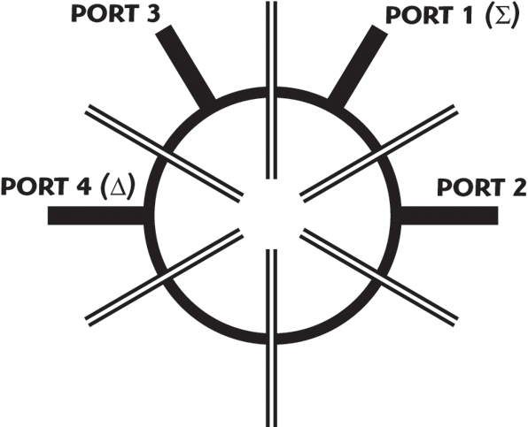
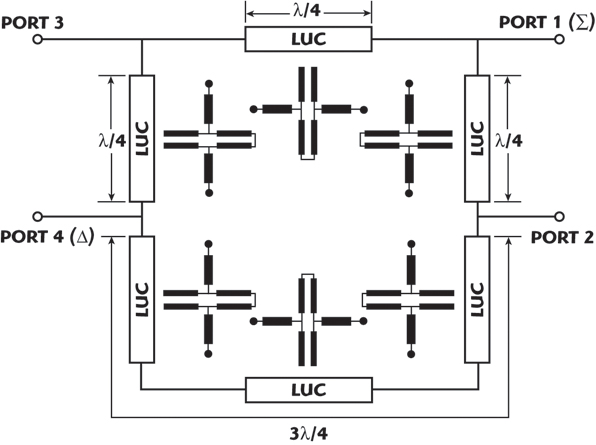
Figure 1 shows the proposed ring hybrid layout; its schematic configuration is shown in Figure 2. Here, the transmission line sections of the conventional ring hybrid are replaced by six LUCs. The LUC and its equivalent transmission line model are shown in Figure 3. A coupled line, shown in the dotted line box, for which the electrical length is λg (4θc) at 3f0, is connected with two short transmission lines (θ1), as shown. The coupled line is considered as a transmission line (θ2).
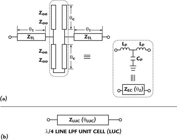
Using Equations 1 to 3 and a process similar to the one reported previously,4 one can obtain the proper LUC, which has the properties of an equivalent λ/4 transmission line (2 θ1 + θ2) with an impedance of 70.7 Ω. The ABCD-parameter of the LUC, [·]LUC, can be defined by the matrix [·]TL and [·]LB for ZTL(θ1) and ZEC(θ2), respectively, as follows:
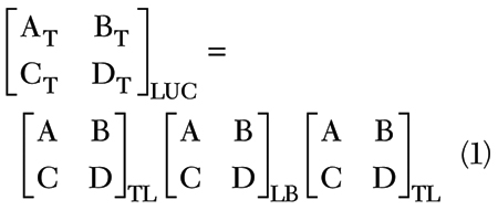

where

The properties of the LUC are shown in Table 1 and Figure 4. The stopband of the LUC is extended up to the fifth harmonic for this hybrid design. Also, the physical length of the LUC is only 8.95 mm, compared to the conventional λ/4 line, which is 19.12 mm at 2.45 GHz, a 53 percent reduction. The miniaturized and harmonic-suppressed hybrid ring can then be designed by using the LUCs instead of the six λ/4 lines of the conventional hybrid.

Simulation and Measurement
The simulated results of the hybrid ring using LUCs, obtained with the circuit simulator ADS™, are shown in Figure 5 and with the EM program HFSS™ in Figure 6. The substrate used is WINUS IS640-338 with a thickness of 0.762 mm, εr = 3.38 and a tan δ = 0.0042. The power division, impedance matching and isolation properties, in the passband at approximately 2.45 GHz, are as good as a conventional one. In the EM simulation, the harmonics are suppressed by more than –23 dB up to 13 GHz.
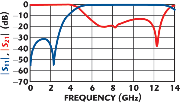
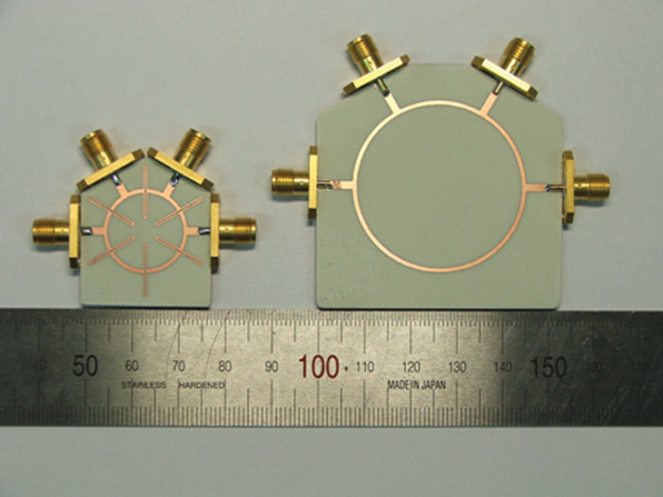
Figure 7 shows a photograph of the proposed and conventional hybrid ring couplers, both having the same center frequency of 2.45 GHz. The area size of the proposed hybrid ring is reduced to one fourth of the conventional one. The measured results are shown in Figure 8. They agree well with the EM simulated results, for power division, matching, isolation and harmonic suppression properties. The measured losses in the passband, including SMA connectors, are 0.20 and 0.31 dB at ports 2 and 3. The reflection coefficient at port 1 and the isolation between port 1 and port 4 are both better than 15 dB. Good in-phase (within ±1.5°) and out-of-phase (180° ±1.5°) characteristics are also obtained

Furthermore, this hybrid ring suppresses not only the third but also the fifth harmonics by more than –20 dB. Considering the simplicity of the structure, this is an important figure of merit compared to the one reported previously.4
Conclusion
A new compact hybrid ring structure is proposed, with significantly reduced size and good harmonic suppression properties, simultaneously. It is based on a simple hairpin-type LUC, showing a broad stopband characteristic. The proposed hybrid ring has not only the same advantages as the one reported previously, but also the additional ability to suppress harmonics, up to the fifth, and also simplicity of the structure and fabrication. The measured and simulated results show high harmonic suppression (> 20 dB) up to 13 GHz without degradation of the passband characteristics (f0 = 2.45 GHz). The ring area size of the proposed ring hybrid is only one fourth of the conventional one.
Acknowledgment
The authors wish to thank AMOTEC Co. Ltd. for its discussion about industrial trends.
References
1. R.K. Settaluri, G. Sundberg, A. Weisshaar and V.K. Tripathi, “Compact Folded Line Rat-race Hybrid Coupler,” IEEE Transactions on Microwave and Guided Wave Letters, Vol. 10, No. 2, February 2000, pp. 61–63.
2. M.L. Chuang, “Miniaturized Ring Coupler of Arbitrary Reduced Size,” IEEE Microwave Wireless Components Letters, Vol. 15, No. 1, January 2005, pp. 16–18.
3. Y.J. Sung, C.S. Ahn and Y.S. Kim, “Size Reduction and Harmonic Suppression of Rat-race Hybrid Coupler Using Defected Ground Structure,” IEEE Microwave Wireless Components Letters, Vol. 14, No. 1, January 2004, pp. 7–9.

4. H.S. Lee, K. Choi and H.Y. Hwang, “A Harmonic and Size Reduced Ring Hybrid Using Coupled Lines,” IEEE Microwave Wireless Components Letters, Vol. 17, No. 4, April 2007, pp. 259–261.
5. H.S. Lee, C.H. Lee and H.Y. Hwang, “A Harmonic Suppressed Design of Size Reduced Ring-hybrid Using Folded Line Structure,” The Journal of Korea Electromagnetic Engineering Society, Vol. 17, No. 9, September 2006, pp. 845–851.
6. H.S. Lee and H.Y. Hwang, “A Size Reduced Ring Hybrid Using Pressed PBG Ring Structure with a Wide Stopband,” 2006 KEES Korean Conference Digest, Vol. 16, No. 1, November 2006, pp. 117–121.
7. S.I. Kim, C.S. Kee, I.M. Park and H. Lim, “Pressed PBG Ring Structure with a Wide Stopband,” The Journal of Korea Electromagnetic Engineering Society, Vol. 13, No. 10, December 2002, pp. 1071–1077.
8. H.S. Lee and H.Y. Hwang, “A Design of Size Reduced Ring Hybrid Using Coupled Lines of Hairpin-type,” The Journal of Korea Electromagnetic Engineering Society, Vol. 18, No. 5, May 2007, pp. 547–551.

Hong-Seop Lee received his BS and MS degrees in electrical and electronic engineering from Kangwon National University in 2005 and 2007, respectively. His research interests include microwave antennas and RF systems.

Hee-Yong Hwang received his BS degrees in biology and electronic engineering from Seoul National University in 1988 and 1992, respectively, and his MS and PhD degrees in electronic engineering from Sogang University in 1995 and 1999, respectively. From March 2000 to February 2001, he was a research professor with the department of electronic engineering at Sogang University. From March 2001 to April 2002, he was a visiting researcher with the ECE department at the University of Maryland, College Park, MD. Since March 2003, he has been an associate professor with the department of electrical and electronics engineering at Kangwon National University, Chuncheon, Korea. His research interests include microwave passive and active components and RF systems.