
The generation of ultra-wideband (UWB) waveforms is of great interest for applications ranging from communications to position sensing. Research and development engineers working in UWB are faced with the challenge of generating unique waveforms that meet their application requirements. Often this also requires high-performance waveforms (very fast transition times with significant amplitudes) and flexible performance. Some of the most common UWB waveforms are presented in this article along with techniques and equipment that may be used to generate them. In this article, UWB waveforms have been classified into four categories: step, rectangular, impulse and monocycle. These waveforms are shown in Figure 1.

Each type of waveform will have its own particular properties. For example, a monocycle has a narrower frequency spectrum than the other waveforms shown and no DC component. Consequently, it is often used with bandwidth-limited antennas. The shape of a waveform also determines its spectral energy.

The graphs in Figure 2 show time domain waveforms and frequency spectra for step pulse generators with added impulse forming networks (IFN). A step generator, producing a 10 V 45 ps risetime step, was used for the measurements. Adding a single IFN to the output of the generator produced the 3 V 50 ps duration impulse. Adding a second IFN resulted in a 1.8 V monocycle. Since the risetimes of the step, the impulse and the monocycle are very similar in this example, the spectra above 10 GHz have the same basic shape. The curves are offset vertically because of resulting amplitude differences (there is some loss in each IFN used). Note, waveforms with slower risetimes will have similar shapes but will be shifted toward lower frequencies.
Three basic hardware tools will be discussed and presented in this article:
• Signal generators, step (positive, negative), rectangular and impulse
• Impulse forming networks (IFN)
• Risetime filters
Together, these tools allow an engineer to generate and shape a waveform while providing a great deal of flexibility. For example, a 10 ps step generator can be combined with risetime filters to produce transition times ranging from 10 ps to many nanoseconds. The same generator may also be combined with IFNs to produce ultra-fast impulses and monocycles (see Figure 3). This type of hardware provides both the highest performance and a wide range of waveform properties with a single set of equipment.

As another example, impulse generators offer a unique combination of impulse amplitude and full-width-half-maximum (FWHM). Figure 4 shows a plot of the generator producing impulses with 60 ps FWHM and 8 V amplitude. In addition, there is often more than one possible implementation for generating the same waveform. For example, an impulse can be generated with a step generator and an IFN, with a rectangular generator and a risetime filter, or directly with an impulse generator. The best choice will depend on the waveform parameters required by the application (for example, transition time, amplitude, duration).
Step Generators
Step waveforms typically have an extremely fast leading edge, a flat topline and a much slower (> 10x) trailing edge. Step generators provide the world’s fastest transition times for commercial electronic pulse generators. Generally, for these generators, a fixed charge line sets the step duration. However, with some step generators the step duration may be adjusted by changing the length of an external charge line.

A typical negative polarity fast step generator waveform is shown in Figure 5. This example produces steps with an ultra-fast falltime at the leading edge (< 5 ps), followed by a fixed duration at –Vamp. Note, the risetime of the signal at the trailing edge is significantly slower than the leading edge falltime and the pulse duration cannot be changed (with this generator architecture). An example positive polarity step generator waveform is shown in Figure 6. Table 1 summarizes the characteristics of several step generators products offered by Picosecond Pulse Labs (PSPL).
Rectangular Pulse Generators
Rectangular pulses with positive polarity have a fast leading edge transition or “risetime” and flat top line. The trailing edge transition or “falltime” is often slower by some amount. A typical rectangular pulse is shown in Figure 7. Rectangular pulse generators are generally programmable over a continuous range of amplitude, offset, duration and frequency. This programmability affords a greater degree of waveform flexibility. The pulse duration or width, td, is measured at the 50 percent amplitude level. This is often referred to as FWHM. Risetimes and falltimes are specified as the transition duration from 10 to 90 percent of Vamp. Table 2 shows these characteristics for PSPL’s rectangular pulse generators.

Impulse Generators
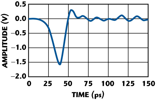
An impulse generator (waveform shown in Figure 8) has the advantage that it produces a single pulse with no opposite polarity impulse corresponding to the trailing edge of the generator’s waveform (compared to a rectangular pulse generator with added IFN). Impulse generators may also produce a differential output. Differential outputs are useful for exciting the two arms of a dipole.
An impulse waveform has a relatively flat spectrum from DC to approximately f–3dB, where


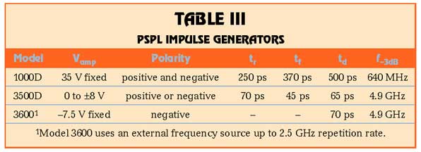
The useful energy extends to more than three times f–3dB. The characteristics of PSPL impulse generators are listed in Table 3.
Impulse Forming Networks (IFN)
An impulse forming network (IFN) is a component that may be connected to the output of a generator. An IFN produces an output that is approximately the derivative of the input. If the input is a step, the output will be an impulse. If the input is an impulse, the output will be a monocycle. Multiple IFNs may be cascaded (for example, to produce a monocycle from a step).

Figure 9 shows the output when an IFN is added to a positive rectangular pulse. Two impulses are created. A positive impulse corresponds to the rising portion of the input signal shown in Figure 6. The Vamp1 is about 25 to 35 percent of Vamp of the input pulse. The duration of the impulse td1 will be slightly wider than the risetime of the input signal.
The output amplitude of an IFN is proportional to dV/dt of the signal at the input. The falltime of the trailing edge of the waveform in Figure 6 is approximately twice as long as the risetime. As a result, Vamp2 of the negative impulse will be 50 percent of the positive one, and td2 for the negative impulse will be about twice as long as td1.
It is important to choose an IFN that is appropriate for the risetime of the signal. If a slow transition signal is combined with an IFN that is designed for fast risetimes, the IFN will not efficiently couple the signal, and the output will be very small. If the risetime of the input signal is too fast for the IFN, the impulse duration will be lengthened, and the waveform shape may be distorted. The recommended risetimes for PSPL’s line of IFN products overlap to give comprehensive risetime coverage, as shown in Figure 10. As an example, one could choose model 5210 or 5212A for use with a 50 ps risetime pulse. The 5212A will produce a larger amplitude output (more efficient coupling), but the impulse duration for the 5210 will be narrower (faster coupling).

IFNs are also very useful when working with fast step generators. In this case, the combination of the fast step transition and the IFN produce a very narrow impulse. Figure 11 shows a typical waveform for a step generator (e.g. PSPL Model 4005) with an added IFN. The negative transition at the leading edge creates a negative polarity impulse. There is effectively no measureable impulse from the much slower trailing edge of the step generator.
Adding two IFNs to a step generator will create a monocycle. When the IFNs are matched to the risetime of the step, one can expect a monocycle with Vpeak-peak that is between 16 and 25 percent of Vamp for the step. A monocycle may also be created by adding an IFN to the output of an impulse generator. It has been found experimentally that the spectrum of a monocycle created with these techniques is relatively flat over the frequency range of


Risetime Filters
A risetime filter is also a component that can be connected to the output of a generator. A risetime filter may be used to slow a signal’s risetime and falltime. A fast pulse generator and risetime filters may be used to produce signals over a wide range of frequency content. In theory, for a Gaussian signal and filter, the aggregate risetime of the pulse and filter is given by

For example, adding a 100 ps risetime filter to a pulse with tr of 45 ps should produce an output with 110 ps risetime. Realistically, pulses and filters are not perfect. However, in practice, the risetime of the combination will be close to this prediction.

The configuration shown in Figure 12 is particularly useful for generating impulses for UWB antenna testing. When the duration of the rectangular pulse is set to about 1.84 times the risetime of the combination of the filter plus the generator, the filter slows the leading and trailing edges so that the output is an impulse instead of a square wave.
There are two advantages to this approach. First, the impulse amplitude is nearly as large as the amplitude of the rectangular pulse. Recall that when an IFN is used, the resulting impulse amplitude is 25 to 33 percent of the amplitude of the rectangular waveform. Second, there is no negative impulse created from the trailing edge of the rectangular pulse, as there would be if an IFN were used.

Risetime filters may also be added to an impulse generator to slow the rising and falling edges. In this case, the impulse duration will increase and the amplitude will decrease. To a first approximation, the area under the impulse curve will remain constant (the product of the amplitude, Vamp, and duration, td, will remain constant).
Figure 13 shows the result of adding a filter with a risetime of 2 x td and one that is 4 x td. The amplitude without a filter is Vamp. The amplitude with the 2 x td filter will be about 0.5 x Vamp. The amplitude with the 4 x td filter will be about 0.25 x Vamp.
Conclusion

Many tools for generating UWB signals are readily available to engineers that are capable of producing step pulses, rectangular pulses, impulses and monocycles. These waveforms can be very high-performance, with step pulses with risetimes < 5 ps and flexible. A combination of generators, impulse forming networks and risetime filters provide a toolbox for both generating a variety of waveform shapes and frequency content. (Note: additional papers entitled “UWB Signal Sources, Antennas & Propagation” and “Picosecond Pulse Generators for UWB Radars” are available on the Picosecond Pulse Labs web site.)