
Product Feature
220 to 325 GHz Vector Network Analysis
Oleson Microwave Labs (OML)
Morgan Hill, CA
A new pair of vector network analyzer (VNA) frequency extension modules, covering 220 to 325 GHz, is being introduced along with a precision waveguide calibration kit. The models V03VNA-T/R and V03VNA-T are compatible with any microwave VNA currently marketed that supports external frequency extension. Vector network analysis applications in the 220 to 325 GHz range are emerging in several areas, including R&D efforts on new 600 GHz and 1 THz semiconductors, NOAA/NASA space borne radiometers for weather prediction and earth resource management, Defense Department space communications and reconnaissance, and characterization of second and third harmonic responses in fiber-optic applications at 80 GHz and higher. Also, there is funded effort underway in millimeter-wave vector network analysis-based DNA studies of biologics. These two new models are part of a family of frequency extension modules covering 33 to 325 GHz in all of the waveguide bands from WR-22 through WR-03.
System Configuration
|
|
|
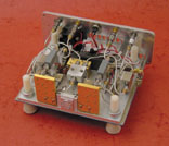
Fig. 1 Interior view of the V03VNA-T/R module |
All current millimeter-wave capable vector network analysis systems employ a VNA that acts not only as the measurement instrument but also as the controller for two external synthesizers and a millimeter-wave controller (module interface). In the millimeter-wave mode the VNA is operated as a four channel fixed frequency receiver tuned to the system's IF. The first synthesizer is programmed by the VNA to provide the RF drive signal and the second synthesizer is programmed to provide the LO drive signal. The millimeter-wave controller provides amplification for the RF, LO and IF signals as necessary and, under the control of the VNA, provides the forward and reverse switching of the RF signal so that all four S-parameters can be measured automatically. Depending on which manufacturer's system is employed the millimeter-wave controller may also supply the DC bias for the frequency extension modules.
The typical system employs two transmission/reflection (T/R) modules to provide simultaneous four parameter (S11 , S21 , S12 , S22 ) measurement capability. A less expensive system with one T/R module and one T module is capable of only measuring S11 and S21 . To obtain S12 and S22 data the user must disconnect the device under test (DUT) from the system, turn the DUT around and reconnect it to the system. The T/R and T combination is very popular for its significantly lower entry cost. The T module can be cost effectively upgraded to a T/R module at a later date. When two T/R modules are used, for S11 and S21 measurement, the first T/R module can be thought of as the dominant module. The multiplier of the first T/R module is the system RF signal source. The reference downconverter of the first T/R module provides the VNA reference signal for the S11 and S21 measurement. The test downconverter in the first T/R module provides the VNA reflection (S11 ) signal and the test downconverter of the second T/R module provides the VNA transmission (S21 ) signal. These roles are reversed for S12 and S22 measurement and the second T/R module becomes the dominant module.
|
|
|
Fig. 2 Simplified block diagrams for the (a) V03VNA-T/R and (b) V03VNA-T modules. |

With a T/R module and a T module combination, the T/R module multiplier is always the system signal source and the T/R module downconverters provide the VNA reference and reflection (S11 ) signals as previously described. The T module downconverter provides the transmission (S21 ) IF signal for the VNA. The T/R and T module combination is popular for passive component testing and has been found to be especially useful for antenna measurement. In an antenna measurement system the T/R module acts as the signal source and allows the measurement of the antenna feed return loss characteristics. The T module, which is small and easy to operate remotely, functions as the receiver front-end for measurement of the antenna pattern characteristics. A third module, the S module, is also available. It contains a signal source and has no measurement downconverter capabilities. It is also popular for use in low cost antenna ranges and has been used as a source combined with a T module for materials measurements.
Module Design
The V03VNA-T/R, shown in Figure 1 , includes a multiplier that acts as the system RF signal source. The input frequency is 18.333 to 27.083 GHz, a commonly available frequency range with the newer VNA systems operating up to 30 GHz. An inexpensive Option x2 adds an additional doubler to the multiplier chain for use with the less expensive 20 GHz synthesizers. The V03VNA-T/R measurement section consists of a dual directional coupler, a reference downconverter and a test downconverter. The directional coupler provides a forward coupled signal (-10 dB) to the reference downconverter and a reverse coupled signal (-10 dB) to the test downconverter. The directivity of the couplers is greater than 30 dB, typically 35 dB. The two downconverters are identical. The mixers employed are subharmonically pumped with a 12.222 to 18.055 GHz LO signal. The level of this LO signal is held constant to each mixer by an LO limiting amplifier to provide good full band frequency response. The mixers are a two diode, single balanced design with an IF between 10 and 300 MHz depending on which VNA system is being extended. The IF noise figure is less than 1.7 dB and the IF gain is set to accommodate the VNA system to be used. A simplified V03VNA-T/R block diagram is shown in Figure 2 .
|
|
|
Fig. 3 System dynamic range achieved with a V03VNA-T/R and V03VNA-T pair. |

The V03VNA-T module utilizes a single downconverter, identical to those used in the T/R module. Unlike the T modules for the lower frequencies, the V03VNA-T 220 to 325 GHz module is operated without an input attenuator. This is done to maximize the system dynamic range, which is typically greater than 50 dB. A plot of system S21 dynamic range is shown in Figure 3 . An optional, maximally flat coupler style attenuator is available to improve the T module input return loss (measurement system load match). Figure 4 shows an interior view of the V03VNAT module. The V03VNA-T/R and V03VNA-T specifications are listed in Table 1 .
Interference Avoidance
The RF and LO harmonic numbers utilized in the frequency plan for these modules were developed to avoid the generation of tracking spurious responses at fixed IF offsets. The VNA commands the RF and LO synthesizers to step from the first RF and LO frequency pair to the next and so on. The size of the frequency steps is determined by the VNA based on the number of data points required. The RF and LO are coherent through the use of a common system reference frequency standard. Older millimeter-wave VNA systems phase locked the LO source to the RF source using the downconverter reference IF signal. There were cases where VNA systems have been configured with the same RF and LO harmonic number and tracking spurious responses were created which fell on the VNA IF input frequency image or related response. When this has occurred, the offending spurious signal has often been of high enough signal level so as to mask the desired signal response to the DUT. By keeping the RF and LO on different harmonic numbers, fixed IF offset spurious responses are avoided as all of the spurious responses continue to change in frequency as the RF and LO pair is stepped. Frequency plans for all of the waveguide bands from 33 to 325 GHz are shown in Table 2 .
|
| |||||||||||||||||||||||||||||||||||||||||||||||||||||||||||||||||||||||||
Calibration
|
|
|
Fig. 4 Interior view of the V03VNA-T module |

The V03CAL Calibration Kit is also being introduced and can support any of the standard waveguide calibration routines. A list of these routines can be found on the company's Web site at www.oml-mmw.com. The V03CAL kit configuration is typical of all of the OML waveguide calibration kits available from 33 to 325 GHz. The kit contains two each precision fixed waveguide loads allowing more precise and convenient measurement of the directivity and isolation terms, two mechanically robust calibration shims (one at 0.1 inch thick and one at 0.1 inch plus 1/4l thick at the waveguide band geometric mean), two each precision flush waveguide shorts for use with the calibration shims and for the measurement of the reflection term, a precision waveguide sliding load for a more precise measurement of the directivity error terms and a precision 1 inch waveguide section for confirmation of the calibration using the time domain technique. Figure 5 shows the V03CAL Calibration Kit and four waveguide band modules covering 60 to 325 GHz.
Conclusion
|
|
|
Fig. 5 The V03CAL calibration kit and four waveguide band modules. |

The addition of the V03VNA modules to the frequency extension module family provides waveguide band coverage from 33 to 325 GHz. The V03VNA modules can be used in S-parameter characterization of passive components, active circuits and semiconductor devices, and in characterization of antenna performance and material properties. When used with OML modules for WR-12, WR-08 and WR-05, contiguous four band coverage from 60 to 325 GHz is available with any microwave VNA currently on the market that is capable of supporting external frequency extension. Additional information on the V03VNA modules and millimeter-wave vector analysis in general can obtained on the company's Web site at www.oml-mmw.com.
Oleson Microwave Labs (OML),
Morgan Hill, CA (408) 779-2698.
Circle No. 304