
TECHNICAL FEATURE
Two Novel Radar Vehicle Detectors for the Replacement of a Conventional Loop Detector
In this article, intrusive and non-intrusive radar vehicle detectors, compatible with existing inductive loop detectors (ILD) without any modification of the communication algorithm, have been developed at 24 GHz. The intrusive detector is based on simple CW radar technology, and the non-intrusive detector on both frequency modulated continuous wave (FMCW) altimeter and Doppler speedometer technologies. With either one of these vehicle detectors, the length and velocity of every vehicle on the road can be detected. Various signal processing circuits have been included. For compatibility with the traffic information network connected with the ILDs, traffic information has been sent to a vehicle detection system (VDS) by using the RS-232C standard interface. The test results show that the intrusive detector development has improved accuracy by 7.1 percent in length and 4.8 percent in speed, while the non-intrusive improved by approximately 8 percent in speed and length over the ILD.
Ihn S. Kim, Key Jeong
and Jae Kwon Jeong
KyungHee University
Suwon, South Korea
Since it has been proved that radar technology is useful in detecting the distance and speed of neighboring objects in air, sea and land14 , the application of this technology to a vehicle detector for collecting information about length and speed of a vehicle passing on the road is a natural extension. Vehicle detectors must provide accurate traffic information even in adverse weather conditions. If the usage of the road can be determined accurately, excellent traffic plans for the future can be established accordingly. As a result, the vehicle detector is an important device for the realization of an intelligent transport system (ITS).
Even though various types of conventional vehicle detectors have their own advantages, they also have their own disadvantages.58 Consequently, there has been a need for an R&D effort to develop a new vehicle detector to overcome the various disadvantages. Among conventional detectors, the ILD has predominantly been used in almost every country.7 However, the most widely used ILD has its disadvantages.7,8 One of them is that it requires too much time to maintain. Also, when this problem is solved, if the existing traffic communication algorithm and network connections with the ILDs are considered, it demands too much manpower and cost. To overcome these problems, two types of vehicle detectors, intrusive9,10 and non-intrusive,11 based on radar technology at 24 GHz, have been developed. The intrusive detector is based on simple CW radar technology and the non-intrusive on both FMCW and Doppler radar technologies. This article introduces in sequence the intrusive and non-intrusive detectors in terms of system configuration and measurement. In the Appendix, the algorithm obtaining traffic information with the ILD has been included for comparison.
INTRUSIVE VEHICLE DETECTION SYSTEM
Since the ILD circuit includes a sensing part which consists of a buried long wire loop over a wide area, it has been prone to become disconnected during the summer months. Also, it has not produced accurate traffic information because of the low frequency used.7,8 Thus, there has been a need for a new detector to overcome these disadvantages. A small sensing area located in the center of a lane on the road bed, along with keeping the same signal processing algorithm as for the ILD for compatibility, have been required.
|
|
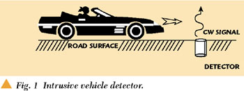
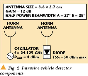
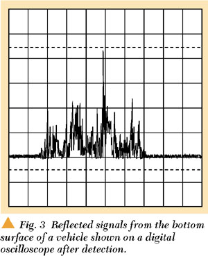
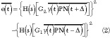
The intrusive detector, installed inside the pavement, transmits CW signals upward with a power level of 3 dBm at 24.125 GHz, as shown in Figure 1. The RF components and their specifications for the detector are shown in Figure 2. Two antenna configurations for transmitting and receiving have been adapted to overcome the spillover problem in a CW radar system.3,4 If there is no vehicle passing over the detector, no reflected signal from the bottom surface of a vehicle will be returned to the detector. When a vehicle is passing over the detector, reflected signals, which appear at the output of the RF receiving diode, are shown in Figure 3. The reflected signal at the input of the diode3 is

where
|
Pr |
= |
received power |
|
Pt |
= |
transmitted power |
|
Ga |
= |
antenna gain |
|
|
= |
wavelength |
|
|
= |
radar cross section |
|
R |
= |
range (the distance between the bottom surface of a vehicle and the detector) |
|
L |
= |
loss of the lines between oscillator and antenna on the transmitter side and between the diode and the antenna on the receiver side |


|
|
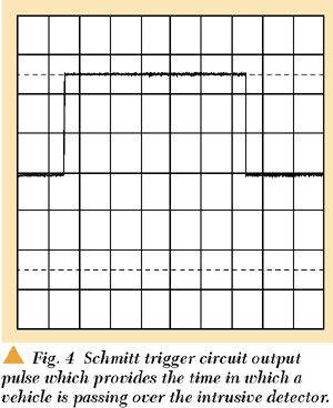
A rectangular shaped pulse, as shown in Figure 4, is obtained as an output pulse by adding the Schmitt trigger circuit shown in Figure 5. The pulse becomes a base signal for digital processing which can measure the length of the vehicle, and its speed is calculated by using two detectors with a known distance separating them in the longitudinal direction as for the ILD.
 |
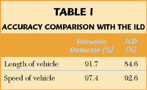
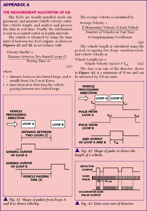
Traffic information has been measured by the detector with the VDS in terms of the accuracy of the speed and length of a vehicle. The ILD was also used for comparison. Appendix A describes the ILD measurement algorithm. The accuracy of the speed was compared with the one taken from a speed gun (model SR-100A) manufactured by Wonsung Electronic Co. The measured data for the length was compared with the exact length of the car as provided by the manufacturer. After 146 vehicles were measured, the averaged measured data and the accuracies were compiled and are listed in Table 1. This new detector shows a 7.1 percent improvement in length accuracy and a 4.8 percent improvement in speed accuracy over the conventional ILD.
 |
NON-INTRUSIVE VEHICLE DETECTION SYSTEM
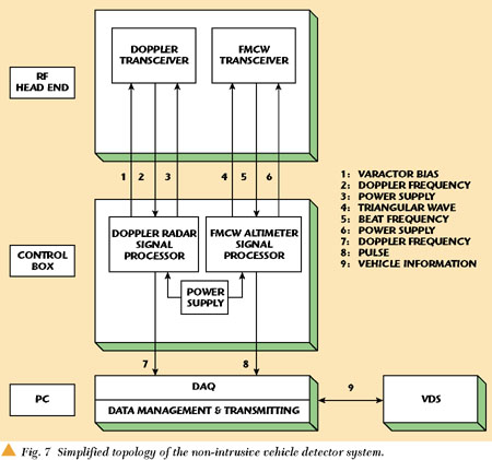
The non-intrusive vehicle detection system, which is another vehicle detector developed to overcome the ILD problems and be compatible with the existing traffic communication algorithm, is operated as shown in Figure 6. The system is usually installed at a height of 4.5 m above ground, and is composed of the FMCW altimeter system, which detects vehicle length by measuring the height from the road surface and the Doppler speedometer system, which detects the velocity of the vehicle. A simplified block diagram for the system function is shown in Figure 7.
|
|

FMCW ALTIMETER
The altimeter is a system measuring distance by means of frequency difference between transmitted and received signals. The transmitter frequency is increased and decreased linearly as time increases, as shown in Figure 8. Distance information (vehicle length) can be obtained by measuring the frequency of reflected signals.24
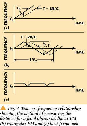 |
The 24 GHz transmitting frequency must be increased linearly in order to measure the distance accurately. If a vehicle is at distance R, the reflected signal will be returned after a time T = 2R/c. In the figure, the dotted line indicates the reflected signal. fb denotes the beat frequency between transmitted and reflected signals, which can be obtained by24
where
|
f0 |
= |
transmitter frequency |
|
Tm = 1/fm |
= |
period of modulation |
|
Δf |
= |
frequency difference between maximum and minimum frequencies of signal |
|
R |
= |
distance from the source to a target |
If the target does not move, the beat frequency is the frequency shift along the distance to the target (no Doppler effect).
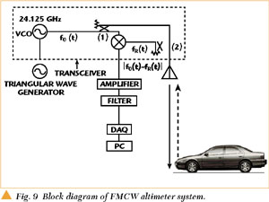
The block diagram of the FMCW altimeter system developed is shown in Figure 9. A triangular frequency modulation, f0 (t), is generated. A 7 dBm output signal from a 10 dBm source in the frequency range between 23.7 and 24.2 GHz is fed through a 3 dB directional coupler (A), and 4 dBm of RF power is radiated through a 21 dB gain horn-antenna after passing through another 3 dB directional coupler (B). This signal will be reflected from the asphalt surface located 4.5 m away. The received signal is approximately 17 dBm. Again, the received signal passes through coupler B and 20 dBm of RF power is applied to the mixer in the receiver. Then, a signal with frequency |f0 (t)-fR (t)| appears at the IF port.
|
|

The signal containing distance information is the beat frequency. Figure 10 is a block diagram which explains the FMCW altimeter function. The IF output signal of the transceiver is amplified with 66 dB gain and passed through a 40 kHz low pass filter, which is the bandwidth of interest. An automatic gain control (AGC) circuit rejects the reflected waves corresponding to distances less than 1.5 m and greater than 4.5 m. A 15.5 kHz signal corresponding to 4.5 m is passed through the bandpass filter (BPF). This frequency is identified as the road surface, and the other frequencies are defined as the presence of a vehicle. To minimize the measuring error caused by the nonlinear characteristic of the transceiver voltage controlled oscillator (VCO), an analog switch is used to obtain a beat frequency exclusively for a voltage range from 3 to 5 V with respect to the triangular source signal. When the road surface is sensed, the signal for a one-shot multivibrator is provided. Then +5 V appears at the output. Consequently, in the absence of a vehicle, an output of 0 V will appear by using a NOT circuit. If there is a vehicle present, +5 V is obtained. At the output interface, a voltage divider circuit is inserted, so a voltage higher than 5 V cannot appear. Therefore, 3 V is applied to the digital acquisition (DAQ) board.
Figure 11 shows the AGC circuit diagram in the FMCW altimeter. The second OP amp is operated as an active rectifier, and the output voltage of the amplifier is applied to the gate port of the FET biased at 0 V. The resistivity, between drain and source, varied by the gate input voltage regulates the first OP amp input voltage. The AGC circuit produces about 0.15 V at the output when an input voltage between 300 mV and 5 V is applied. If the input voltage is higher than 5 V, the output waveform will be distorted.
|
|

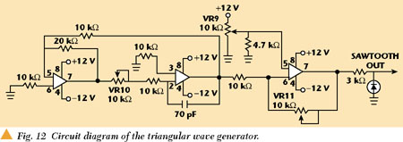
The circuit diagram of the triangular wave generator for FM modulation is shown in Figure 12. The first OP amp oscillates because of a positive feedback, the second OP amp acts as an integrator and the third OP amp controls the offset voltage. VR9, VR10 and VR11 are variable resistors to control frequency, offset voltage and amplitude, respectively. The frequency of the generator is variable from 390 to 650 Hz, and the amplitude is also variable up to 12 V.
DOPPLER SPEEDOMETER
If a target moves at a given velocity, the frequency of the reflected signal will shift from the transmitted frequency by the Doppler effect. If an angle  exists between a target, and the radar and the velocity v of the target is defined, then the frequency shift between the transmitted and reflected signals can be obtained by24

In this development the Doppler radar has been installed at a height of 4.5 m as a speedometer and facing the road at about 60°.
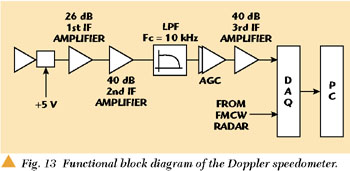
Figure 13 shows the functional block diagram of the Doppler radar, which is similar to that of the FMCW altimeter without the triangular wave generator. AGC has been inserted to obtain a constant output independent of distance variation. After the second 40 dB gain amplifier, the signal is applied to the DAQ board.
|
|
MEASUREMENT RESULTS FOR THE NON-INTRUSIVE DETECTOR
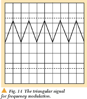
Figure 14 shows a triangular waveform ranging from 0.5 to 12 V at 500 Hz for operating the VCO.
In the transceiver, the input voltage range of the VCO is from 0.5 to 20 V, but the linearity of the transceiver is not good above 12 V. Therefore, the voltage of the triangular wave is limited to 12 V for the transceiver to operate only in the frequency range from 23.70 to 24.24 GHz.
|
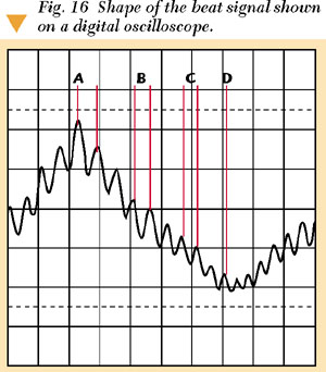
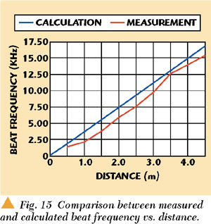
Figure 15 shows a comparison of the calculated and measured frequencies with respect to the distance with a bandwidth of Δf = 540 MHz (0.5 to 12 V) and at a modulation frequency fm = 500 Hz. However, because of the nonlinearity of the transceiver, the relation of the beat frequency versus distance is not perfectly linear. The amplitude and phase of the beat frequency superimposed on the triangular wave at the output port of the first IF amplifier is shown in Figure 16. A digital oscilloscope has been used to verify that the amplitude and phase of the beat frequency are constant. However, because of nonlinearity, the beat frequency overlaps in a 500 Hz triangular wave, A, B, C and D, as shown in the figure, indicate frequencies which are varied in the range from 8.3 to 12.5 kHz.
Finally, the inductive loop detector and this system have been installed at a place on the road. The lengths and velocities of vehicles passing over have been measured with this system, a loop detector and a speed gun, all at the same time, as shown in Figure 17.
|
|

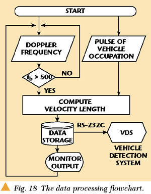
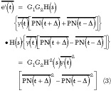
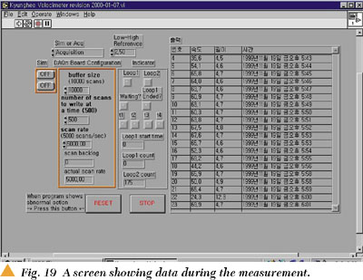
Figure 18 shows the flowchart of the data processing program using LabView.12 The velocity can be obtained from Equation 3 by

and the length of vehicle is given by L = v x  , where is the occupation time. Data for the length and velocity are displayed through a PC monitor with LabView, as shown in Figure 19.
 |
Ninety vehicles have been tested with the system on the road. Approximately 98 percent and 90 percent accuracies have been obtained for the velocity and length information, respectively. Ninety-eight percent is almost the same as the accuracy of the speed guns. This means that, if compared with the existing ILD, approximately an 8 percent improvement has been achieved in accuracy. Appendix B shows data for eight different vehicles selected randomly from the ninety vehicles.11
For compatibility with the existing traffic information network, whenever a vehicle is detected, the system sends its velocity and length data to a VDS console port by using the RS-232C standard interface.
CONCLUSION
Two types of radar vehicle detectors, intrusive and non-intrusive, the front-end for the ITS infrastructure, have been developed using simple CW radar, FMCW altimeter and Doppler speedometer technologies in order to overcome the ILD problems. These detectors can be a replacement for the ILD and directly connected to the VDS without any change in the communication algorithm. Test results show that the intrusive detector has an improved accuracy, by 7.1 percent in vehicle length and 4.8 percent in speed, and the non-intrusive one, by approximately 8 percent in both speed and length, over that of an ILD. Unlike the image processing detectors, the characteristics of these systems cannot be affected by fog, smoke, and day and night transition. To minimize the measuring error caused by the nonlinear characteristics of the transceiver VCO in the non-intrusive system, an analog switch is used to control the beat frequency for the voltage range from 3 to 5 V with respect to the triangular source signal, so the vehicle occupation and non-occupation are detected accurately. A low price, high performance and low weight altimeter with minimum nonlinearity in the VCO, using a micro controller unit (MCU) to replace the PC for signal processing, and a vehicle detector which obtains vehicle velocity and length by using only one transceiver, are planned. The intrusive detector can be used to check the presence of a vehicle in a parking area. *

References
1. A.G. Stove, "Obstacle Detection Radar for Cars," Electronics & Communication Engineering Journal, October 1991, pp. 232240.
2. H.D. Griffits, "New Ideas in FM Radar," Electronics & Communication Engineering Journal, October 1990, pp. 185194.
3. M. Skolnik, Introduction to Radar Systems, Second Edition, McGraw Hill, New York, 1990.
4. M. Skolnik, Radar Handbook, McGraw Hill, New York, 1989, pp. 1427.
5. D. Fenihell, et al., "Advanced Traffic Detection: Emerging Technologies and Market," Transport Technology Publishing, 1995.
6. G.L. Duckworth, M.L. Frey, C.E. Reme, S. Ritter and G. Vidaver, "Comparative Study of Non-intrusive Traffic Monitoring Sensors," SPIE, Vol. 2344, Intelligent Vehicle Highway Systems, 1994, pp. 1629.
7. ITE (Institute of Transport Engineers), "Traffic Detector Handbook," Second Edition, Washington D.C., 1990.
8. Traffic Control Systems Handbook, U.S. Department of Transportation Engineer, December 1985.
9. Ihn S. Kim, "In-pavement Radar Type Vehicle Detector using mm-wave," Korean Patent No. 0214447, 1998.
10. Jae Young Jung and Ihn S. Kim, "Development of a New Vehicle Detector Combining CW Radar and Magnetometer Techniques," The Journal of Korea Electromagnetic Engineering Society, August 1999, Vol. 10, No. 4, pp. 564581.
11. Ihn S. Kim, "Development of a New Vehicle Detector by Using Low Power Radio Wave," Research Report for Korea Highway Corp., December 1999.
12. L.K. Wells, The LabView Student Edition User's Guide, Prentice Hall, 1995
|
Ihn S. Kim received his BE degree in electrical engineering from KyungHee University in 1974, and his MASc and PhD degrees, both in electrical engineering, from the University of Ottawa in 1991. He has worked for the Canadian Space Agency, Com Dev Ltd., General Instrument of Canada and the Korean Broadcasting System. He is currently a professor in the school of electronics and information at KyungHee University in Korea. His research involves commercial application of radar technology, modeling of microwave structures by time domain numerical methods (FDTD and TLM) and its application to filters and power dividers/combiners, and nonlinear microwave circuit development such as oscillators and mixers. Mr. Kim can be reached at ihnkim@khu.ac.kr or +82-31-201-2587. Key Jeong received his BS degree in physics and his MS degree in electrical engineering from KyungHee University, Suwon, Korea, in 1998 and 2001, respectively. His research interests are in the area of radar system and microwave mixer (direct conversion). In February 2001, he joined Samsung Electronic Co. as a hardware design engineer for the W-CDMA Team.. Jae Kwon Jeong received his BS degree in electrical engineering from KyungHee University, Suwon, Korea, in 1999. He is currently working on his MS degree, also in electrical engineering, at KyungHee University. His research interests are the areas in vehicle collision avoidance radar and microwave oscillators. |