
Over the last four decades, the use of wireless technology has become so pervasive, both militarily and commercially, that we have come to rely upon its never-ending, and seemingly unbounded, ability to carry more and more information. Despite our ever-increasing appetite, the fundamental principles for managing access to the spectrum, established over a century ago, by and large still hold. Today, the wireless spectrum is still divvied up through a manual and time- intensive process of assignment and licensing. Over the last several years, commercial wireless use of the spectrum has been growing at a CAGR of 45 to 50 percent.1 Yet, our radio systems remain locked into their approved frequency bands, unable to dynamically respond to the ever-changing demand placed on the wireless spectrum.
In the now fully crystallized modern era of artificial intelligence (AI), where we find AI managing stock trades, labeling pictures of faces and driving cars, it seems oddly out of place and antiquated that we do not find AI with a role in the increasingly crowded wireless spectrum. To address this obvious shortcoming, and enable continued growth and spectrum usage both militarily and commercially, DARPA created the Spectrum Collaboration Challenge (SC2). SC2 is an open competition that invites competitors to re-imagine the spectrum landscape without predetermined “lanes,” instead explore the intersection of AI and software-defined radios (SDR) to enable a spectrum landscape where radio systems autonomously and collaboratively self-organize, self-govern and self-optimize the spectrum’s usage—not on intolerably slow human timescales, but second-to-second, on machine timescales.
Unlike making an autonomous vehicle, making a single radio smart enough to find an unused wireless frequency is fairly trivial. However, the wireless spectrum is not one radio; it is a sea of many varied and different radios. For autonomy to be truly successful in the wireless spectrum, we need ensemble autonomy. That is, we need to answer the question: “What happens when hundreds of radios, each with their own waveforms, signal processing and distinct decision-making engines, occupy the same spectrum?” Will the spectrum turn into a chaotic bumping, colliding, trampling crowd and ultimately become unusable? Or, will order emerge like a colony of ants?
To answer these questions, we needed a new type of RF test environment, one that allows AI to interact at scale, in real-time and in an environment that emulates real world RF conditions. Our response was the creation of Colosseum, the world’s largest RF channel emulator- based testbed constructed for DARPA’s SC2.
In this article, we discuss the design and implementation of Colosseum, including the architectural choices and trades required to create an internet-based radio development and test environment of this scope and scale.
COLOSSEUM REQUIREMENTS
Within the context of the SC2 competition, Colosseum serves as a development and test environment for the competitors as well as a battleground to determine which AI-enabled radio design reigns supreme. A handful of key requirements guide Colosseum, enabling the SC2 competition while creating a valuable national asset for use beyond the competition:
Large scale—To study ensemble AI requires large numbers of independent actors, in our case radios, interacting in real-time. To do this, we need the ability to connect 100+ SDRs in a realistic RF environment. This requires the emulation of RF multipath that mimicks the phenomenon of a radio transmission bouncing off environmental obstacles be- fore reaching one or more receivers.
Full mesh—The autonomous engines of each radio have the potential to impact every other radio operating in the same geographic area. This demands that Colosseum be constructed as a “full mesh,” or in a way that every radio is able to hear every other radio, each through a unique RF channel.
Wideband—Even if we are successful, spectrum autonomy will not be given carte blanche access to the entirety of the spectrum initially, rather constrained to a small region of the spectrum until it has earned its stripes. To that end, Colosseum must emulate wireless interactions across a reason- ably wide bandwidth of 80 MHz.
Neighborhood sized—Lastly, a congested spectrum environment, where each radio’s probability of potentially harming another radio’s communication is highest, is most stressful for this type of autonomy. We want the ability to emulate a reasonable, but not overly large, area of an urban neighborhood— approximately 1 sq. km.
CHALLENGE OF LARGE-SCALE CHANNEL EMULATION
Colosseum comprises two over- arching constituent components (see Figure 1): a pool of SDR resources, which SC2 competitors use as a common platform to build their intelligent radios, and a massive channel emulator (MCHEM) that emulates the interactions of radio waves in the physical world, with sufficient veracity so that from any one radio’s perspective, it appears to be operating in an open-air environment.
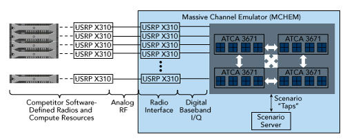
Figure 1 Colosseum block diagram.
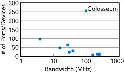
Figure 2 Colosseum requires modeling many more ports than existing channel emulators.
The radio resource pool comprises off-the-shelf Ettus Research USRP X310 SDRs mated with commodity rack servers. The real engineering challenge in bringing Colosseum to life lies largely with the creation of the MCHEM. There are no channel emulators currently in the market capable of supporting the computation and bandwidth needed to compute the interactions of hundreds of radios in real-time (see Figure 2). As such, Colosseum had to be custom designed and built. The real-time nature, sheer data throughput and digital signal processing (DSP) computation eliminates any solution based on general purpose processors (GPP) or even state-of-the-art graphics processing units (GPU). Colosseum’s channel emulation needs were met with FPGA processing hardware. Further, to keep the cost low and minimize the development time required to solve this gargantuan computing problem, Colosseum had to be based on existing off-the-shelf products.
The following sections introduce the basic principles of digital channel emulation, quantitatively expand on the computing requirements and map this design to existing hardware.
DIGITAL CHANNEL EMULATION 101
To understand what the MCHEM does, it is important to understand the basics of channel emulation. Imagine you are in a large empty hall; when you shout, your voice echoes throughout. If your friends were listening to you at different points in the building, at each point they would hear a very different version of your voice. This happens be- cause depending on where you are listening, your voice collides with different surfaces, creating a distinct echo pattern. This same phenomenon happens when we transmit wireless communications into a complex indoor or outdoor environment. The channel is the distinct set of objects a waveform (voice or wireless) interacts with be- tween a transmitter and receiver.
Extending our hall example a bit further, imagine 256 people in the hall, all talking at the same time and trying to pass information to each other. Some voices are deep while some are squeaky high, with perhaps a dozen different languages being spoken. The sound that each person hears is the combination of all 256 people in the room and all the reflections or echoes. Emulating this example in real-time for wireless signals is what Colosseum must do, but at a tremendous scale.
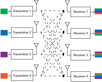
Figure 3 Example showing contributions from each of four formation to each transmitters to each of four receivers.
Figure 3 shows a graphic representation of four radio transmitters and four receivers operating simultaneously. The wireless channel between them governs the interactions between the various transmitters and receivers. The channel can be modeled mathematically, with each transmitter providing a unique contribution to each receiver that is identical to a dot product. When we consider multiple transmitters, this forms a matrix product where each term represents RF multipath, or the attenuation and delay created by wireless echoes.
KEY DESIGN PARAMETERS
To satisfy Colosseum’s four key requirements, one must first comprehend the scale of computational complexity imposed by them:
To satisfy the requirement for large-scale, 256 radio inputs and outputs are used. The system has 20.48 GHz of bandwidth, input and output or 102.4 GB/s of data throughput.
For full mesh functionality, every transmitter must interact with every receiver. We must represent a unique RF path between every transmitter and receiver pair, thus resulting in 2562 or 65,536 paths. This is what truly sets Colosseum apart from today’s existing channel emulators. Delay paths are usually modeled in the digital world with finite impulse response (FIR) filters. A key design parameter is how many taps (i.e., unique echoes) each FIR filter should use. More taps provide a more realistic emulation, as they allow for modeling more paths be- tween the source and receiver, but they also increase computational complexity. The 3GPP community published standard channel models for LTE testing, some with as many as nine taps (i.e., the extended vehicle model). With the primary focus of the SC2 competition on AI, the compromise was to give up some modeling fidelity and use only four taps per FIR filter. This still results in an enormous computation load of 157 tera-operations per second (TOps).
One of the key requirements is to be wideband (i.e., have high instantaneous bandwidth). Supporting 80 MHz is a reasonable compromise between bandwidth, cost and com- putational complexity. To achieve 80 MHz of instantaneous RF band- width, the MCHEM fractionally over- samples the required bandwidth to 100 MSPS. Assuming quadrature (I/Q) sampling with 16 bit samples, each MCHEM input and output has to simultaneously receive and transmit 400 MB/s.
Radio waves traverse the physical world at the speed of light. To produce accurate delay to account for the time of flight of a signal going from one end of the neighbor- hood to the other, memory is need- ed to buffer the signal. Light takes 3.33 μs to travel 1 km. To buffer 3.33 μs worth of digital samples at the chosen 100 MS/s requires a buffer of 312 samples. Rounding up to the nearest power of 2, a buffer of 512 samples is used, which equates to a maximum delay of 5.1 μs.