
A new family of +12 V power amplifiers designed for use in wireless infrastucture applications has been introduced. The models AP501, AP502, AP503 and AP504 are targeted for driver and final stage amplifier applications where high linearity and high power are primary requirements. The combination of high power and high linearity makes these new amplifiers excellent candidates for multi-carrier 2.5/3G, PCS, UMTS and CDMA2000 base station use.
The new AP-series devices are multi-stage modules developed using the InGaP HBT process that are internally optimized for efficiency and linearity performance. Each of the PA modules includes internal matching for input and output 50 W operation and operates from a 12 V DC supply without requiring negative biasing voltages. In addition, an internal active bias allows the devices to maintain high linearity of a full range of operating temperatures.
The AP-series devices are designed to optimize the back-off linearity characteristics by setting the bias point to give a fast decrease of ACLR without backing-off too much in output power. A typical ACLR vs. output power curve of the AP-series is shown in Figure 1. As a result, a lower P1dB device can be used to generate the same linear power with excellent ACLR. This is the most cost effective way to generate a linear power for the driver stage of the power amplifier where a stringent linearity is required.
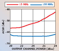
Fig. 1 Typical ACLR vs. channel power performance for 3GPP W-CDMA operation at 2140 MHz.
The AP-series PA modules have the added feature of a +5 V power down control pin. A functional diagram and pin identification table of the AP-series PA modules is shown in Figure 2.
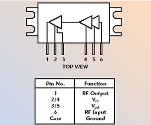
Fig. 2 The AP-series PA module’s functional block diagram and pinouts.
PA Performance
The AP501 PCS-band PA module uses a high reliability InGaP/GaAs HBT process technology and is designed to operate from 1930 to 1990 MHz with 30.5 dB of gain. The device features +36 dBm P1dB and +52 dBm output IP3. It is capable of +29 dBm IS-95 linear power at –50 dBc adjacent channel power ratio (ACPR) with 9 percent efficiency or +25.5 dBm W-CDMA linear power (–50 dBc adjacent channel leakage ratio (ACLR)) with 8.5 percent efficiency.
The AP502 UTMS-band PA module operates from 2110 to 2170 MHz with 28 dB of gain. It supplies +36 dBm at P1dB and +52 dBm at its OIP3. The device provides +27 dBm of W-CDMA linear power output (+45 dBc ACPR).
The AP503 DCS-band unit operates from 1805 to 1880 MHz with 31.5 dB of gain. Its CDMA2k linear power is +27 dBm (–60 dBc ACPR) and its IS-95A linear power is +26.5 dBm (–55 dBc ACPR). The AP504 DCS-band amplifier module operates from 1710 to 1785 MHz with 31.5 dB of gain and similar linear power performance to its AP503 sister amplifier.
Figure 3 shows ACPR performance at 1960 MHz for IS-95, while Figure 4 shows ACPR performance at 1840 MHz for CDMA2000 operation.

Fig. 3 Typical ACPR vs. channel power performance for IS-95 operation at 1960 MHz.

Fig. 4 Typical ACPR vs. channel power performance for CDMA2000 operation at 1840 MHz.
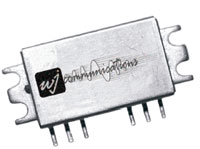
A low cost 29 × 13 × 4 mm metal housing with a bolt-down flange allows these devices to maintain a low thermal resistance and thus achieve an MTTF of over 100 years. In addition, the devices are 100 percent RF and DC tested. Fully assembled device samples are available upon request. Additional information can be obtained from the factory or from the company’s Web site.
WJ Communications Inc.,
San Jose, CA
(408) 577-6200,
www.wj.com.