

Electronically steered phased arrays are increasingly deployed in satellite user terminals to support high-throughput links, rapid beam steering and operation under motion. Fully digital beamforming offers maximum flexibility but does not scale efficiently in cost, power consumption or clock distribution complexity. Purely analog beamforming is power-efficient but limited in adaptability, calibration and interference mitigation.1,2
This article explains why hybrid phased arrays, which combine analog sub-arrays with digital beamforming, represent the most practical architecture for next-generation satellite user terminals. Emphasis is placed on deployment-relevant differentiators: localized PLL-based frequency generation for phase noise and coherence control, receive-side spatial processing for beam tracking and interference mitigation and improved calibration enabled by greater observability. The relevance of these capabilities to emerging 5G non-terrestrial network (NTN) operating conditions is examined, along with how hybrid arrays may be combined with AI techniques to further improve system-level performance.
The rapid expansion of non-geostationary satellite constellations has fundamentally changed user-terminal antenna requirements. Terminals must track fast-moving satellites, operate under platform motion and maintain performance in increasingly congested spectrum, while meeting stringent constraints on cost, size and power. Electronically steered phased arrays are the only practical solution for many of these use cases. However, the choice between analog, digital and hybrid beamforming architectures strongly influences whether a terminal can be realized and manufactured at scale.
The Starlink constellation, now serving approximately nine million subscribers as of December 2025, many using second- or third-generation terminals, represents the only true mass market deployment of phased array antenna technology. These terminals integrate several hundred RF integrated circuits (ICs) to drive antenna elements, along with multiple beamformer devices. Public disclosures indicate that SpaceX has worked with STMicroelectronics to deliver a low-cost, high volume solution using SiGe BiCMOS technology. Teardown analyses consistently indicate that this architecture is neither fully digital nor purely analog, but a hybrid beamforming solution.
In parallel, the move toward standards-based 5G NTN OFDM waveforms increases sensitivity to phase noise and common phase error. NTN beam management assumptions also imply narrower beams, faster updates and frequent refinement under relative motion. Dense multi-constellation operation further elevates the importance of interference detection and spatial mitigation at the terminal. While these factors do not mandate a specific antenna architecture, they favor solutions that combine RF efficiency with sufficient digital control to support beam refinement, tracking and resilience to interference and jamming.
ANALOG AND DIGITAL BEAMFORMING: NEITHER IS IDEAL ON ITS OWN
Pure analog beamforming remains attractive due to its simplicity and power efficiency. Phase shifting and gain control are performed close to the antenna elements, minimizing losses and power consumption. For smaller arrays with narrowband signals or slowly varying links, this approach can be adequate.
As bandwidth and dynamics increase, however, analog beamforming becomes a limiting factor. Beam squint increases with bandwidth; calibration capability is limited and more demanding for larger arrays; and there is limited spatial visibility on the receive path. Interference mitigation is largely confined to static patterns or slow, coarse adaptation. Scaling a pure analog beamformer for different array sizes requires bespoke RF combining/splitting and routing for each array.
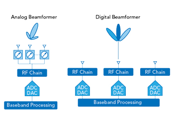
Figure 1 Analog vs. digital beamforming: Analog architecture minimizes hardware and power by combining signals in the RF domain, whereas digital architectures provide fine-grained beam control by digitizing each antenna path, significantly increasing processing and system complexity.
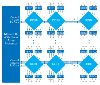
Figure 2 Representative hybrid phased-array architecture with DDBF controlling multiple RF IC sub-arrays. This partitioning localizes RF complexity while retaining sufficient digital observability for beam control, calibration and receive-side spatial processing.
Fully digital beamforming offers the opposite trade-off. By digitizing every antenna element, it enables multiple beams, adaptive nulling, fine-grained calibration and advanced spatial algorithms. In practice, the required number of high speed data converters, their associated power consumption and the complexity of distributing low-jitter clocks and local oscillators (LOs) across dense Ka- and Ku-Band arrays render this approach impractical for most user terminals (see Figure 1). Hybrid beamforming exists because the extremes of fully analog and fully digital do not serve the real world.
WHAT “HYBRID” REALLY MEANS IN A TERMINAL CONTEXT
In a hybrid phased array, beamforming is partitioned across two domains:
- Analog beamforming is applied locally within small sub-arrays, typically inside RFICs located close to the antenna elements.
- Digital beamforming operates across the outputs of these sub-arrays, rather than across individual elements.
This architectural split substantially reduces the number of digital channels required, while preserving enough spatial information to support advanced beam control, interference mitigation and receive-side processing.
Crucially, hybrid architecture also allows frequency generation and phase-coherence to be localized. Phase-locked loops (PLLs) can be integrated within the distributed digital beamformer (DDBF) IC, where they generate or discipline local clocks for each sub-array. This reduces long-distance clock distribution, limits phase noise accumulation and improves coherence across temperature, voltage and aging variations (see Figure 2).
In practical terms:
- RF routing remains short, local and highly repeatable.
- Clock and RF LO distribution are localized through PLLs integrated within the DDBF. Only digitized signals traverse the full array or panel.
- Array size is scaled through replication of identical tiles or sub-arrays.
- Calibration observability and long-term stability are significantly improved.
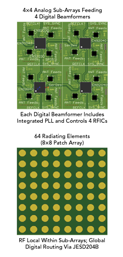
Figure 3 Hybrid 64-element Ka-Band receive phased-array panel. An 8×8 patch aperture is served by four analog sub-arrays, each controlled by a digital beamformer with integrated PLL and interconnected via JESD204B.
The hybrid ratio, defined as the number of analog element paths combined per digital channel, is not fixed and varies with system architecture (see Figure 3). While Figures 2 and 3 illustrate a 4:1 example, practical phased arrays may employ substantially higher ratios, up to 256:1 or greater in large arrays (e.g., > 1024 elements), reflecting trade-offs between cost, power consumption, digital processing complexity, calibration observability and interference mitigation capability, and the ratios used for transmit and receive paths need not be the same. Some of the advantages discussed diminish the higher the hybrid ratio gets.
PHASE NOISE, COHERENCE AND THE BENEFIT OF LOCAL PLLS IN HYBRID ARRAYS
In large phased arrays, phase noise is fundamentally a system-level issue rather than a component level specification.3 Loss of phase-coherence across the aperture directly reduces coherent gain, beam pointing accuracy and achievable null depth, while in wideband and OFDM-based waveforms it also degrades EVM and increases spectral regrowth. These effects are amplified at Ka-Band, where narrow beams, high-order modulation and environmental variability place stringent demands on phase stability.
Hybrid phased array architectures address these challenges by enabling localized frequency generation. Rather than distributing a high frequency Ka-Band local oscillator across the antenna panel, a low frequency reference clock is distributed and multiplied locally using PLLs integrated within RF beamformer or DDBF ICs serving individual sub-arrays. This architectural shift moves phase noise optimization from the component level to the array level.
Although an individual integrated PLL may not, in isolation, meet the full Ka-Band ETSI DVB phase noise mask, hybrid arrays combine signals from multiple independently clocked sub-arrays. The dominant phase noise contributions are largely uncorrelated and therefore average down when combined coherently across the aperture. As illustrated by the Ka-Band simulation results in Figure 4, compliance with ETSI DVB phase noise requirements can be achieved using only 16 distributed local low-power and low performance PLLs, delivering equivalent array level performance with an approximately 80 percent power saving compared to a single state-of-the-art COTS PLL.
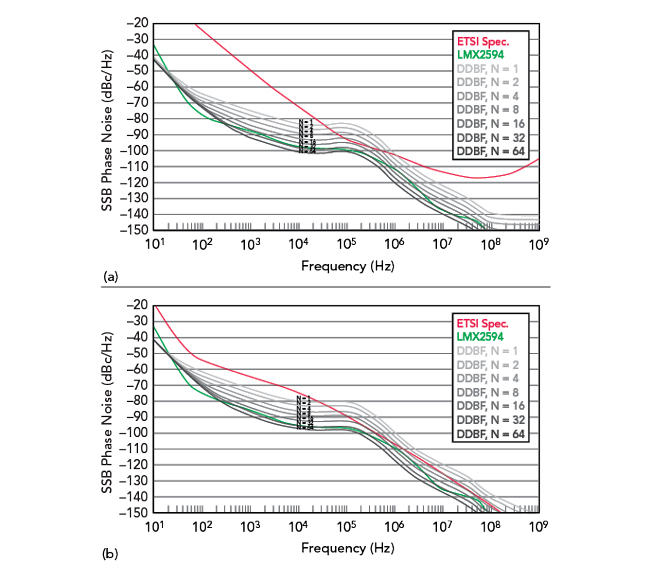
Figure 4 Ka-Band Rx 20 GHz (a) and Ka-Band Tx 30 GHz (b) phase noise versus offset frequency, showing ETSI DVB requirements compared with the combined phase noise of multiple DDBF PLLs for different numbers of PLLs (N = 1 to 64), and a state-of-the-art COTS PLL (LMX2594).
Beyond phase noise performance, local PLL integration shortens LO paths, reducing sensitivity to PCB parasitics, coupling and temperature gradients — significantly simplifying clock and LO distribution at Ka-Band. This improves robustness in mobile and environmentally variable deployments, while further reducing system power consumption and implementation complexity, key advantages for scalable, high volume Ka-Band hybrid phased array terminals.
RECEIVE-SIDE PROCESSING IN HYBRID PHASED ARRAYS
Hybrid phased arrays preserve useful spatial information on the receive path without requiring per-element digitization. Each sub-array output can be treated as a virtual antenna element, providing the digital processor with a reduced dimension yet spatially meaningful representation of the incoming wavefield. This representation enables several receive-side functions of growing importance in modern satellite user terminals, including blind acquisition, beam refinement and tracking, interference detection, localization, adaptive beam and null steering. Together, these capabilities improve link robustness under real operating conditions and are particularly relevant for high-availability systems operating under motion or in interference-dense environments.
The number of resolvable spatial directions in a hybrid array is fundamentally limited by the number of digital receive channels, which correspond to the number of sub-array outputs. A practical rule of thumb is that a hybrid array with K digital receive channels can typically resolve up to K–1 independent signal directions, including the desired signal and interferers. In practice, modest values of K, for example, four to eight channels, are sufficient for typical terminal scenarios, such as tracking a desired satellite beam while detecting one or more dominant interferers or adjacent satellites.
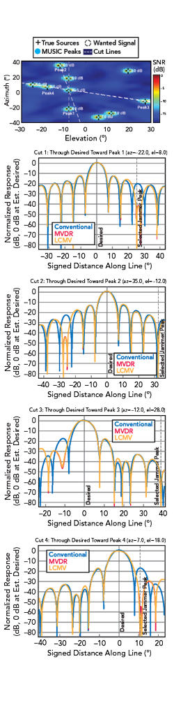
Figure 5 An example of a 16x16 element hybrid array (hybrid ratio 64:1) performing acquisition and interference mitigation.
Classical direction-of-arrival (DoA) algorithms, such as MUSIC and ESPRIT, are well-established in array-processing theory but are rarely implemented in textbook form in terminal systems. In hybrid arrays, these techniques are typically adapted to operate on sub-array outputs rather than individual elements, constrain the search space using prior knowledge (such as expected satellite direction), operate intermittently to limit computational load and combine with simpler techniques, such as monopulse-style error sensing, for rapid tracking. The objective is not super-resolution, but sufficient angular awareness to support tracking, interference localization and null placement in real time. An example is shown in Figure 5. The array is used as a time-multiplexed compressed spatial sensor to determine signal sources and their DoA. Wanted and interference signals are then classified and adaptive beamforming techniques, including minimum variance distortionless response (MVDR) or linear constrained minimum variance (LCMV), applied to implement null steering. The top of Figure 5 shows signal sources and their DoA. As can be seen in the subsequent antenna pattern cuts, significant interference/jammer rejection can be achieved over and above a conventional array, leading to improved overall performance
For terminals subject to motion, including automotive and aeronautical platforms, hybrid arrays enable fine closed-loop beam tracking by estimating the signal arrival direction and dynamically correcting beam pointing. This reduces pointing error without resorting to excessively wide beams, improving effective signal-to-noise ratio.
In dense LEO environments, the same spatial awareness can be used to identify interferer directions, separate them from the desired signal and apply spatial nulls through digital weighting across the array. Because these functions are implemented digitally, they can be updated rapidly and coordinated with higher-level beam management strategies.
Machine learning (ML)-assisted spatial spectrum estimation and DoA techniques4 can further improve practical resolution and robustness under low signal-to-noise ratio and calibration error. When only a limited number of sub-arrays are available, these approaches enhance the reliability of interferer localization, without increasing hardware complexity.
CALIBRATION: ADVANTAGES OF HYBRID BEAMFORMING
Calibration is a primary limiter of phased array performance.5 Beam pointing accuracy, sidelobe control, null depth and wideband fidelity all depend on correcting frequency-dependent amplitude, phase and timing errors across the array. In highly integrated systems, these errors vary with temperature, operating state and aging, making calibration a continuous system requirement rather than a one-time production step.
Hybrid phased array architectures simplify calibration by combining local analog signal paths with distributed digital observability. Constraining RF routing within tiles or sub-arrays reduces sensitivity to PCB parasitics, coupling and thermal gradients, improving repeatability and stability across the aperture. This immediately reduces both the magnitude and variability of the errors that must be corrected at the system level.
At the same time, hybrid arrays provide sufficient digital visibility without requiring full per-element digitization. Effective calibration does not require direct access to the raw RF signals of every element. Instead, relative gain, phase and timing errors can be estimated and accumulated at the sub-array level, provided the array partitioning, reference distribution and digital aggregation are designed coherently. This avoids the power, data-movement and implementation complexity associated with fully digital arrays.
These properties make in situ and over-the-air calibration practical and scalable. Rather than relying on chamber-based, per-unit calibration that does not scale to high volume terminals, hybrid arrays can maintain calibration during deployment using known signals, mutual coupling and network-assisted procedures. This enables compensation for slow drift caused by temperature variation, mechanical stress and aging over the operational lifetime of the terminal.
At the system-level, AI/ML techniques can be used as a supervisory layer to model predictable calibration drift and update the correction coefficients over time. Used in this way, AI complements deterministic calibration rather than replacing it, reducing recalibration frequency and enabling continuous in-field optimization without increasing hardware complexity or data bandwidth. When calibration is treated as a system-level design function rather than a production afterthought, hybrid phased arrays can deliver digital-like performance with lower power, lower complexity and far greater scalability than fully digital alternatives.
RELEVANCE TO 5G NTN OPERATING CONDITIONS
5G NTN work has formalized operating conditions that increasingly reflect modern satellite systems, particularly in LEO. These include rapid time-variation due to satellite motion, tighter tolerances to phase noise and frequency errors driven by wideband OFDM waveforms, more frequent beam updates and refinements, along with operation in dense interference environments.
From an antenna and RF perspective, these conditions increase the importance of maintaining array coherence, enabling agile beam control and retaining sufficient spatial observability on the receive path. While no single beamforming architecture is prescribed, these conditions expose the limitations of purely analog arrays and increase the cost and power burden of fully digital solutions.
Hybrid phased arrays align well with these NTN-style conditions. Local analog beamforming combined with digital control across sub-arrays supports fast, software-driven beam refinement while preserving RF efficiency. Localized frequency synthesis aids coherence for wideband OFDM waveforms, and hybrid receive processing provides sufficient spatial information for interference mitigation without per-element digitization. The key point is not that 5G NTN requires hybrid beamforming, but that NTN operating assumptions reinforce the architectural case for hybrid phased arrays in next-generation satellite user terminals.
CONCLUSION
Hybrid beamforming has emerged as the most compelling architecture for cost and power-constrained satellite user terminals because it directly addresses the practical limitations that prevent purely analog arrays from scaling. It preserves RF efficiency and compactness while introducing just enough digital capability to enable beam refinement, interference awareness, null steering and scalable in-field calibration.
As terminals move toward wider bandwidths, higher thermal variation and more interference-dense operating environments, performance is increasingly determined by system-level effects rather than static RF design. Hybrid arrays provide a reduced-dimensional but information-rich digital view of the aperture, making adaptive, software-defined control practical without the hardware complexity of per-element digitization.
Within this framework, data-driven and ML-assisted techniques can complement established signal processing by tracking slow calibration drift, compensating for temperature-dependent behavior and stabilizing beam tracking and interference mitigation under marginal conditions. Crucially, these techniques operate at the sub-array level, aligning naturally with hybrid architectures.
By combining manufacturable approaches to phase noise and coherence with adaptive system-level control, hybrid phased arrays deliver digital-grade performance where it matters most without the cost, power and integration penalties of fully digital solutions. This is making hybrid beamforming a pragmatic and forward-compatible foundation for next-generation satellite user terminals.
References
- R. J. Mailloux, “Phased array antenna handbook,” Third Ed. Boston: Artech House, 2017.
- C. Fulton et al., “Digital Phased Arrays: Challenges and Opportunities,” Proceedings of the IEEE, Vol. 104, Issue 3, March 2016.
- T. Höhne and V. Ranki, “Phase Noise in Beamforming,” IEEE Transactions on Wireless Communication, Vol. 9, No. 12, December 2010.
- H. Al-Kassir et al, “A Review of the State of the Art and Future Challenges of Deep Learning-Based Beamforming,” IEEE Access, Vol. 10, August 2022.
- G. He, X. Gao and R. Zhang, “Impact Analysis and Calibration Methods of Excitation Errors for Phased Array Antennas,” IEEE Access, Vol. 9, April 2021.