
As satellite ground segment architectures evolve to support higher bandwidths, multi-orbit networks and greater operational flexibility, traditional analog intermediate frequency (IF) distribution is becoming a constraint. Digitization enables scalable, packet-based transport of IF signals, but without common interfaces, it risks recreating proprietary lock-in within digital architectures. The Digital IF Interoperability (DIFI) standard addresses this challenge by defining vendor-agnostic interfaces for digitized IF data and associated metadata. This article provides an engineering overview of DIFI, including its protocol structure, Information Classes and packet types used to transport RF data across IP networks. Key system design considerations such as Ethernet capacity planning, timing synchronization, flow control and link establishment are examined, together with the role of interoperability testing and PlugFest validation. Practical migration strategies for hybrid analog–digital ground segment architectures are also discussed.
Analog IF distribution has formed the backbone of satellite ground segment architectures for decades. In conventional designs, RF front-ends, switching matrixes and processing equipment are connected through fixed, point-to-point coaxial or waveguide infrastructure. This approach has delivered deterministic behavior and well-understood performance characteristics, along with inherent interoperability through the common L-Band IF interface.
However, contemporary ground stations increasingly face significantly wider instantaneous bandwidths, higher channel density and the need to support multiple orbital regimes simultaneously, including GEO, MEO and LEO constellations. These operational demands are compounded by requirements for rapid reconfiguration and the integration of virtualized and software-defined processing environments. As a result, architectural flexibility is no longer optional but fundamental to system scalability.
In analog systems, scaling typically requires additional physical infrastructure. As channel counts and routing complexity increase, hardware constraints begin to dominate architectural decisions. Rack space in teleports is charged by the area consumed, adding OPEX cost to the CAPEX costs of physical modems.
Digitization of IF offers an alternative paradigm. By converting IF signals into packetized data streams, signal routing can be abstracted from physical topology. However, digitization alone does not ensure interoperability.
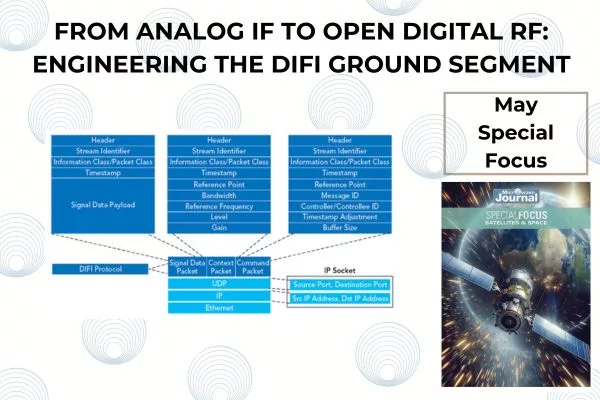
The transition from analog to digital IF architectures is illustrated conceptually in Figure 1. Digitization does not inherently create open systems. Without common interface definitions, digital architectures risk recreating lock-in at the protocol level. Early standards such as V49.2 created a framework for interoperability, but the benefits of this were obviated by manufacturers’ use of vendor-specific extensions.
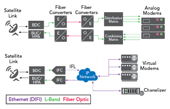
Figure 1 Analog versus digital IF ground segment signal chain comparison.
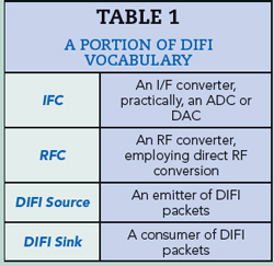
This challenge motivated the formation of the DIFI industry consortium under the governance of Industry Standards and Technology Organization, and the development of the DIFI standard. DIFI has its own vocabulary, which will be used throughout this document. A portion of that vocabulary is in Table 1.
Digitization of IF: Architectural Benefits and Limitations
Digitized IF enables RF signals to be transported across packet-based infrastructure such as Ethernet/IP networks. Digitizing IF enables signal routing to be performed logically rather than through fixed physical wiring, allowing systems to move away from rigid point-to-point topologies. Processing resources can be centralized or distributed depending on mission requirements, and bandwidth allocation can be adjusted dynamically in response to operational demand. In addition, digitized IF architectures align naturally with software-defined and virtualized processing environments, enabling tighter integration between RF transport and higher-layer system control.
Architecturally, DIFI sits at the boundary between IFCs or RFCs and downstream processing systems, as illustrated in Figure 2. Early digital IF implementations frequently relied on proprietary packet structures and metadata definitions. Although signals were digitized, interoperability across vendors was limited. DIFI seeks to solve this with a coherent interoperable approach agreed by a wide variety of industry stakeholders.
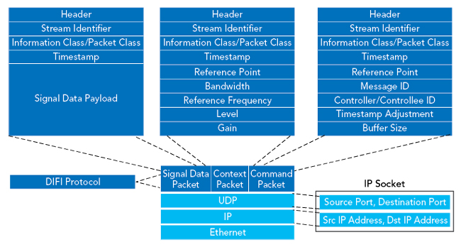
Figure 2 DIFI within the protocol stack.
Proper Ethernet network planning is essential for a DIFI system. Consideration of the required Ethernet bandwidths is essential. Inter-facility links are likely to be 100 to 400 GbE. Intrasite links are likely to be 10 GbE, or for low RF bandwidths 1 GbE. The Ethernet bandwidth requirements are proportional to the RF bandwidth, which in turn determines the sample rate, and (less obviously) to the required dynamic range, which determines the required bit depth. The DIFI protocol is flexible, allowing trade-offs among these parameters.
DIFI Protocol Overview
DIFI defines a standardized interface for digitized IF data and associated metadata. It specifies packet structure and metadata semantics while remaining agnostic to RF front-end implementation, transport topology and signal processing algorithms.
The DIFI protocol is layered on top of UDP over IP. UDP is selected to ensure a deterministic latency. The protocol comprises three packet types: signal data packets, context packets and command packets. These are linked by a common stream identifier (SID), uniquely assigned to each RF signal described by that information stream.
The signal data packets comprise I/Q samples, along with a timestamp which dictates either the time at which the first of the incoming data samples were received or, in the case of the transmit direction, the time at which the first sample is to be transmitted. The context packet contains metadata that describes the RF signal. Parameters such as center frequency, bandwidth, gain and sample rate are all provided to allow the received signal to be accurately reconstructed. Finally, command packets perform a variety of coordination functions such as flow control, link establishment and session management.
The packet types are linked by a common SID. The SIDs allow for many different RF signals to co-exist on the same IP network.
Importantly, DIFI, as with any good protocol, does not define the transport protocols or wide area timing distribution mechanisms (although recommendations on this are included in the standard). It defines how digitized IF data and associated metadata are structured and should be interpreted.
Information Classes
DIFI is based on a set of structured Information Classes (ICs). Each IC contains a number of Packet Classes, which are described in unambiguous detail in the specification. The transfer of an IF signal from one endpoint to another is achieved using an information stream. Each information stream comprises a collection of packet streams, linked by their SID.
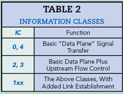
Each IC provides a specified set of functions. This can be seen summarized (some have been omitted for clarity) in Table 2.
Whenever a new version of the DIFI specification is released, it is always done in a backwardly compatible manner.
IC0 and IC4 assume that all devices in the system share a common reference plane. This means that all sample clocks throughout the system are synchronized. These two classes differ in how they timestamp their samples. IC0 gives an absolute fractional picosecond timestamp, while IC4 uses sample count. In each case, the timing is reset based on a 1PPS clock. The source of this clock will be discussed later. This same approach to sample timing exists throughout the more complex ICs, which use this “Basic Data Plane” as their foundation.
This is generally not the case when interfacing with a software modem implemented on a COTS compute platform (CPU or GPU-accelerated), whether cloud-based or local. There is a possibility that such a device could overwhelm the buffers of a digitizer, which must necessarily unload them under sample rate constraints. IC2 and IC3 introduce command packets to implement flow control. More than a simple stop/go system, the sink provides the source information about its buffer size, Buffer fill level and flags indicating overflow, underflow, nearly full and nearly empty.
Information Classes 0x1xx layer link establishment on top of the capabilities already described. Noting that DIFI enables interoperability between equipment from different vendors, there is some opportunity for capability mismatches. The DIFI specification allows equipment to operate at a sample rate of its own choice. Simple, low-cost equipment may elect to use only a single, low sample rate, while more complex equipment may support a much wider variety of rates. A similar potential for mismatch exists with parameters such as bandwidth, frequency and gain.
The complexity of link establishment is further increased when the system includes devices such as electronically steerable antennas, where available bandwidth or gain may vary with look angle or the number of beams being accommodated and capabilities may vary in real time.
Link establishment is a stateful process that incorporates session maintenance, whereby a DIFI source sends a “Sink Capabilities Query Control Packet” to a DIFI sink. The DIFI sink responds with a list of capabilities that it supports. Capabilities include sample rate, frequency, bandwidth and buffer size, along with link session parameters such as “link active timeout.”
Following confirmation of a compatible set of link parameters, the link starts with the transmission of the first signal flow context packet. Signal data packets follow and the link remains active until torn down by the DIFI source. The session maintenance element of the link establishment process allows for a graceful teardown of the link in the event of data famine or malformed context packets received by the DIFI sink.
It is important when specifying DIFI components to consider which ICs are required in the system. As the specification is backward-compatible, it is perfectly reasonable for a system to use only the ICs specified in a prior release if (for example) features such as link establishment are not required.
Transport, Timing and Synchronization Considerations
As satellite frequencies increase, the effect of precipitation becomes increasingly pronounced and plays an important part in link budget planning. Geospatial diversity is a technique employed to mitigate this, calling for geographical separation of ground stations transmitting the same data in the order of 100 km.
In analog IF systems, this is achieved via a fiber-optic link. Here, timing relationships are typically implicit in physical signal paths. A stable 10 MHz reference is required at each site, and a delay/dispersion compensation fiber is inserted in the signal path at the “local” site, to manage the additional delay. We can consider this to be a form of blind compensation for a parameter that can be easily determined and is constant throughout system operation.
One of the benefits of DIFI is the ability to transfer data in real time over significant distances without signal degradation proportional to the distance. That benefit brings its own challenges. Firstly, the sampled signal needs to be released at a precise time at both sites to compensate for the signal transit time between the sites. In the digital domain, this is purely a sample delay buffer. The DIFI protocol supports delays through timestamps relative to a 1 PPS signal. Thus, a wide area 1 PPS reference is required. This can be achieved through GNSS, IRIG-B, PTP or Sync-E. Each of these sources has its own level of accuracy and jitter, and it is important for the system designer to ensure these are suitable for their use case.
A key point about any IP-based system is that network delay is not necessarily deterministic. Sources of delay variance range from the time through different processes within a computer to the paths taken through the network. This is a system engineering task that cannot be neglected and will affect latency, which must be large enough to compensate not only for the late arrival but also for the time required to re-order packets to ensure correct signal reconstruction.
A feature introduced in release 1.3.0 of the DIFI protocol can aid in determining and monitoring the round-trip network delay. A new command packet (Sink Capabilities Query Extension Control Packet (Short Form)) introduced in this revision of the standard contains a calibration field into which a DIFI sink can insert a calibration time, based on the timestamp of the received packet, and the time at which the sink received the packet. When transmitted back to the source, monitoring of the delay in each direction is available, and this can be fed up to Monitoring and Control Systems to enable system-wide decisions on overall latency.
Interoperability Versus Interchangeability
Interoperability enables systems to exchange data using agreed formats and semantics. Interchangeability implies that components can be substituted without modifying the system. DIFI enables interoperability among compliant systems. It does not guarantee interchangeability.
Differences in supported ICs, profile implementations, timing assumptions and performance characteristics may require integration effort. Standards reduce integration complexity. They do not eliminate the need for detailed systems engineering.
Development and Testing of the DIFI Standard
The DIFI standard is developed by the DIFI Specification Working Group. This group comprises stakeholders from across the DIFI consortium, representing a wide range of companies throughout the membership. This ranges from government bodies through satellite operators and equipment manufacturers. A range of features is allocated to each release of the standard to allow incremental development.
The DIFI consortium typically arranges a PlugFest around six to nine months after the release of an iteration of the standard. This gives vendors time to develop this functionality into their products. PlugFest serves not only to allow vendors to assess the interoperability of their equipment with others, but also to test the standard itself. As a (relatively) nascent standard in a developing market, it would be inappropriate to assume that the standard can be released without testing.
The interoperability test configuration is shown in Figure 3. Common references are provided for all equipment. Analog switch matrixes allow the connection of analog test sources to DIFI devices that require them, and they also connect the outputs of DIFI equipment to analog measurement devices. Each DIFI source is connected to each DIFI sink in turn, establishing interoperability.
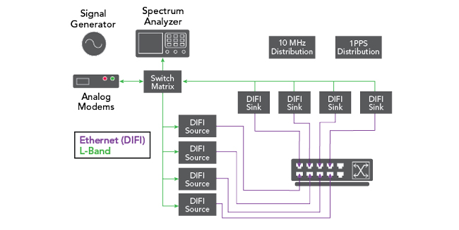
Figure 3 DIFI PlugFest test environment.
These exercises validate conformance to packet structure definitions, correct interpretation of metadata fields and alignment of supported profiles between vendors. They are designed to confirm that implementations adhere to the specification and can exchange digitized IF streams reliably under controlled conditions. PlugFest results are fed back into the Specification Working Group to evaluate what (if any) changes or clarifications are required in the specification.
Having passed through the PlugFest, the DIFI Certification Working Group develops a test regime to allow certification to that set of ICs. DIFI devices do not have to be certified for every IC. Similarly, the certification does not test every combination of sample rate and bit depth. A limited number of combinations are defined, known as profiles, which bound the scope of the certification testing.
Hybrid Architectures and Migration Strategies
Few ground segments transition directly from analog to fully digital IF architectures. Hybrid approaches are common. It is possible to continue to use elements of extant infrastructure while leveraging the benefits of the digital transformation.
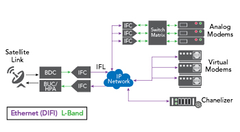
Figure 4 Hybrid analog/digital ground segment migration architecture.
One such example is using additional IFCs in conjunction with analog matrixes to allow, for example, the use of legacy analog modems, as shown in Figure 4. This allows existing L-Band modems to co-exist alongside new digital equipment.
Typical migration strategies involve introducing digital IF at aggregation points within the ground station while retaining analog distribution for selected legacy subsystems. In many cases, migration proceeds incrementally on a mission-by-mission basis, allowing digital and analog architectures to co-exist during transitional phases.
A representative hybrid architecture is shown in Figure 4. Digital transformation should be driven by operational need rather than technology adoption alone.
Common Pitfalls in Digital IF Deployment
As digital RF architectures mature, several recurring challenges have emerged. It is important to specify what ICs are required for the system being defined. A simple point-to-point system may not require the additional costs and complexities of a system with all link establishment functionality. DIFI systems should be specified in terms of the ICs they need, rather than the current release of the standard. While the standard is evolving, it will always remain backwardly compatible.
The size of the required Ethernet infrastructure should be considered carefully. Specifying a 10 GbE network may be sufficient for now, but planning a higher speed network will future-proof investments and help ensure that unexpected errors do not occur. It is not enough merely to consider the required bandwidth for the DIFI link, but allowances must be made for other Ethernet traffic.
Conclusion
Open digital RF architectures represent a significant shift in ground segment engineering. DIFI provides a structured, vendor-agnostic interface enabling interoperable digitized IF exchange.
Successful deployment requires a clear definition of supported capabilities at the system level, including explicit agreement on selected ICs and mode of operation. It also demands a robust timing architecture designed to accommodate transport latency and synchronization constraints, rather than assuming deterministic behavior. Profile alignment between interconnected systems must be verified in advance of integration, and interoperability claims should be supported by rigorous validation under representative operating conditions.
Digitization changes the engineering problem. It does not remove it. Open interfaces create architectural flexibility. Engineering discipline determines performance.