

MULTI-PORT ANTENNA MODULE
To achieve wide angular coverage, a three-port pattern diversity system is designed to achieve hemispherical coverage based on the beamwidth available from the constituent elements. The gain of a single element is a reasonable compromise between angular coverage and gain for a specific user. The antenna system must be physically compact, as well, to match the dimensional constraints from the base station module.
The schematic of the pattern diversity module is shown in Figure 7. The antenna elements are mounted at ± 45 degrees. To enhance coverage, angular separation is optimized. The antennas are mounted onto a dielectric scaffolding, which could be easily manufactured using 3D printing. The overall dimensions of the module are 23 x 10 x 7.3 mm, providing a compact footprint.
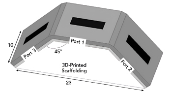
Figure 7 Antenna element schematic. Dimensions are in mm.
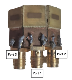
Figure 8 Photograph of the fabricated prototype module.
The fabricated prototype is shown in Figure 8. Three unidirectional antennas are mounted on an additively manufactured dielectric scaffolding. The ground plane is continuous, which minimizes the back lobe. Each antenna element is soldered to a standard SMA connector. The connector introduces 1 to 2 dB of loss. A solderless high-efficiency connector was not used for measurements due to the limitations in the module dimensions.
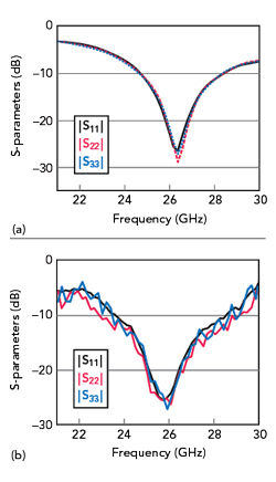
Figure 9 Input reflection coefficients of the module’s constituent antennas: simulated (a) and measured (b).
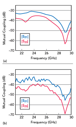
Figure 10 Mutual coupling between the ports: simulated (a) and measured (b).
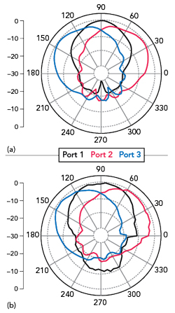
Figure 11 Module radiation patterns for different port excitations at 26 GHz: simulated (a) and measured (b).
A fused deposition modeling technique is used to realize the dielectric scaffolding. The surface resolution is around 200 microns, and the infill ratio is 80 percent. It must be noted that the presence of the additively manufactured scaffolding does not hamper the performance of the pattern diversity module. This could be attributed to the electrically large continuous ground plane.
Input reflection coefficients of the constituent antennas are shown in Figure 9. Impedance integrity is maintained across the ports over the operating band within the n258 5G band.
Simulated and measured mutual coupling between adjacent antenna elements is shown in Figure 10. Mutual coupling between the adjacent ports is less than -30 dB, despite a shared contiguous ground plane. This could be attributed to the pure radiation mode of the constituent antennas. Mutual coupling between the non-adjacent elements is less than -35 dB across the operating band due to the higher electrical separation between them.
Radiation patterns for each of the antennas at 26 GHz are shown in Figure 11. The pattern diversity module achieves an angular coverage of ±80 degrees. Note, also, that the constituent antenna elements maintain pattern integrity within the proposed module. The front-to-back ratio is > 15 dB across the ports, similar to the individual antenna’s behavior.
Simulated 3D polar patterns at 26 GHz for each antenna are shown in Figure 12. Hemispherical coverage is clearly demonstrated, and the gain of the constituent elements is also maintained when the respective port is excited.
CONCLUSION
A wideband unidirectional aperture-coupled antenna element is realized with two substrates of two different thicknesses. It operates in the n258 band with an input impedance bandwidth of 13.6 percent centered at 26 GHz. Within the n258 band, the antenna element has a peak gain of 6 dBi. A multi-port pattern diversity module using three of these antenna elements offers hemispherical coverage with isolation > 30 dB between the antenna ports and across the operational bandwidth. The antenna module is a potential candidate for mmWave 5G base station applications.
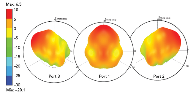
Figure 12 Simulated 3D polar patterns of the module at 26 GHz.
References
- “Cisco Annual Internet Report (2018–2023),” White Paper, Cisco, San Jose, Calif., 2020.
- T. S. Rappaport, S. Sun, R. Mayzus, H. Zhao, Y. Azar, K. Wang, G. N. Wong, J. K. Schulz, M. Samimi and F. Gutierrez, “Millimeter Wave Mobile Communications for 5G Cellular: It Will Work!” IEEE Access, Vol. 1, May 2013, pp. 335–349.
- S. X. Ta, H. Choo and I. Park, “Broadband Printed-Dipole Antenna and Its Arrays for 5G Applications,” IEEE Antennas and Wireless Propagation Letters, Vol. 16, May 2017, pp. 2183–2186.
- S. X. Ta and I. Park, “Compact Wideband Circularly Polarized Patch Antenna Array Using Metasurface,” IEEE Antennas and Wireless Propagation Letters, Vol. 16, March 2017, pp. 1932–1936.
- A. Iqbal, A. Smida, N. K. Mallat, R. Ghayoula, I. Elfergani, J. Rodriguez and S. Kim, “Frequency and Pattern Reconfigurable Antenna for Emerging Wireless Communication Systems,” Electronics, Vol. 8, No. 4, April 2019.
- D. Anandkumar and R. G. Sangeetha, “Design and Analysis of Aperture Coupled Microstrip Patch Antenna for Radar Applications,” International Journal of Intelligent Networks, Vol. 1, No. 4, January 2020, pp. 141–147.