
Antennas convert electrical signals into radio waves. Patch microstrip antennas are specialized transmission and reception microwave systems used in applications including civil, automotive and military radar, cellular networks, Wi-Fi networks, satcom, automotive guidance systems, ballistic guidance systems and space vehicles. A patch antenna system typically consists of two or more overlapping elements, each separated by a layer of dielectric material, as shown in Figure 1.
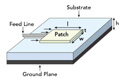
Figure 1 Example of a patch antenna.
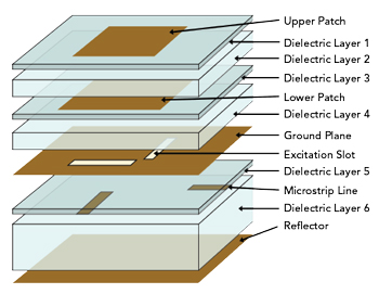
Figure 2 Example of patch antenna layers.
The radiating patch is usually located on the top layer, and other patches, the ground plane with the slot and the microstrip are located in the intermediate layers, as shown in Figure 2.
Patch antennas are very compact compared to traditional antennas; however, they have only modest gain and reduced bandwidth. Recent development efforts have focused on overcoming these limitations with advances in the choice of dielectric, the shape of the patches, the distance between the various planes and the slot coupling system.
The dielectric influences the performance of the antenna and is dependent on the dielectric constant Dk and the dissipation factor Df of the dielectric. Optimal values of Dk and Df are found in the air; therefore, the use of synthetic foams with a high air content offers a solution to the problem of layer spacing in a precise, rigid and economical way.
The foams currently available for these applications have a high air content, with a density range from 20 kg/m3 to 90 kg/m3. Due to the closed-cell structure, they are less affected by humidity and have a dielectric constant close to 1 (similar to air). Thus, foam-dielectric, multilayer patches improve the performance, bandwidth and directionality of the antenna.
Additional gains arise when foam dielectrics are used with a mix of laminates, such as FR4, PTFE, ceramic and hybrid, to create multilayer antennas, which are subsequently processed with plated through holes and then milled into various shapes, as shown in Figure 3.
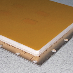
Figure 3 Example of a hybrid PCB antenna with Rogers RO4003C, foam spacer and Kapton.
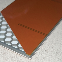
Figure 4 Example of microstrip with Rogers RO4350B, honeycomb spacer and Kapton.
In addition to the foam explained above, BasElectron is developing the honeycomb dielectric, a new solution using a material available with varying Dk values and a Df of 0.005, see Figure 4. This Df value improves signal integrity, increases power efficiency and improves thermal management, which are key factors for patch antennas.
BasElectron designs and manufactures printed circuit board (PCB) circuits in addition to patch antennas. They can satisfy requirements including single-sided, double-sided, multilayer (up to 24 layers), flexible and rigid-flex boards. They have the ability to produce samples in 24 to 48 hours and serve a variety of industries. BasElectron specializes in capabilities including the production of flex PCBs with aluminum heat sinks, planar transformers, PCBs for harsh environments, blind and buried vias, Teflon PCBs, ceramic PCBs, woven glass PCBs, high power PCBs and LED-lighting PCBs.
BasElectron has a range of capabilities allowing them to build their highest track of 600 µm, a thickest PCB of 25 mm and a thinnest PCB of a tenth of a millimeter. They have a range of high-fidelity lab production equipment and test setups to meet a variety of customer needs.
BasElectron SRL
Pavia, Italy
www.baselectron.com