
Modern electronic warfare (EW) systems continue to push toward higher operating frequencies, higher RF power and increased packaging density to meet aggressive size, weight and power constraints. As a result, a typical line-replaceable unit (LRU) may contain dozens of microwave cable assemblies routed near sensitive receivers, high-power devices and digital subsystems. To meet density requirements and ease installation, designers often select push-on interfaces rather than threaded connectors with full-sized coupling nuts, since push-on solutions offer reduced center-to-center spacing.
The density advantage, however, can come with an electromagnetic compatibility (EMC) penalty. In general, push-on connectors offer lower shielding effectiveness than properly torqued threaded connectors due to their design. Push-on connectors have exposed gaps at the mating interface, which increase RF leakage. In addition, push-on connectors are more susceptible to improper installation at the mating interface — partial engagement or angular misalignment — which can further degrade shielding effectiveness, increase VSWR and increase insertion loss.
The threaded SMPM provides a compromise between large threaded connectors and push-on alternatives. The threaded SMPM uses a compact coupling nut that covers the exposed gaps at the SMPM interface, improving EMC. The compact size of the coupling nut supports dense packaging applications while providing a locking mechanism between the mating connectors, reducing installation variability and maintaining performance in use.
EMC CONSIDERATIONS OF COAX CONNECTORS
The increasing number of microwave assemblies within LRUs presents a challenge for system engineers addressing electromagnetic compatibility concerns. As the number of subsystems within a single LRU increases, assemblies are routed closely together and near components operating at high RF power and high frequencies. Electromagnetic interference (EMI) concerns for coax assemblies can be considered reciprocal, as an assembly can be both vulnerable to interference from surrounding components and a potential source of interference.1
Noise from external EMI is coupled into a coax assembly through gaps in the outer conductor shield. These gaps can occur within the connectors, cable or the solder termination between the connector and cable. When external noise penetrates a coax assembly, it induces a signal on the inner conductor that propagates along the line with the desired signal. This acts as interference in a system, decreasing the signal-to-noise ratio and interfering with key EW requirements.
Shielding effectiveness describes a transmission line’s ability to withstand external EMI and limit radiated RF power. It is a standardized metric that allows the performance of different cable assemblies and connectors to be directly compared. For RF characterization, shielding effectiveness can be measured using the mode-stirred method detailed in ANSI/EIA-364-66B-2025.2 A test sample is placed within a shielded metal chamber, where transmitting antennas radiate power into the chamber and induce a signal on the sample. This signal is compared to a measured reference value, and the resulting ratio, given in dB, is the shielding effectiveness, with larger values indicating better shielding.
A useful metric for comparing microwave connectors and assemblies is the requirement defined in MIL-T-81490A (AS),3 which specifies a minimum shielding effectiveness of 90 dB. EMI on a cable is generally considered insignificant if the shielding effectiveness reaches 90 dB or higher in applications through 18 GHz. Depending on the system design, EMI becomes more challenging to manage above 18 GHz, and the minimum shielding effectiveness requirement can be lowered. Each LRU has unique signal requirements, cable routing and connector spacing constraints that impact the choice of connectors and the allowable shielding effectiveness.
CONNECTOR CONSIDERATIONS FOR EW SYSTEMS
Threaded Connectors and Push-On Alternatives
Since push-on connectors offer higher packaging density than traditional threaded options, system engineers often prioritize them. Threaded connectors are density-limited by their coupling nuts. For example, an SMA connector, typically rated to 26.5 GHz, has a 0.3125 in. hex size coupling nut (i.e., wrench flats) per MIL-STD-348B.4 For frequencies through 40 GHz, a 2.92 mm connector is a popular alternative but is also limited by the coupling nut. The 2.92 mm connector is specified in IEEE 287.15 with a 0.315 in. hex size. The actual center-to-center spacing for threaded connectors is larger than the hex size because the corners of a coupling nut exceed the wrench flat width. These values vary between manufacturers, so the hex size is used in this discussion as a common reference.
The SMPM interface demonstrates low VSWR through 40 GHz while enabling tighter connector spacing compared to 2.92 mm and SMA connectors. While the overall diameter of an SMPM socket is not defined by MIL-STD-348B, the microwave connector industry has converged on a typical value of 0.125 in. for standard cable connectors. This results in a 60 percent increase in interconnect density compared to the hex size of a 2.92 mm connector’s coupling nut.
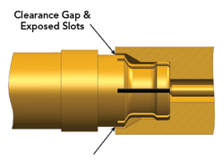
Figure 1 SMPM socket connector mated to a smooth bore pin connector.
The SMPM socket interface is designed with a slotted outer conductor that flexes inward when engaging the mating pin connector. The connector’s flexed fingers apply a radial outward force against the outer conductor of the pin, making an electrical connection. This radial force provides limited retention between the connectors and partially mitigates the need for a coupling nut, simplifying assembly installation. Figure 1 shows an SMPM socket connector mated with a smooth bore pin connector. The socket version is one of W. L. Gore & Associates, Inc.’s standard SMPM connectors and the pin model is drawn to the nominal MIL-STD-348B dimensions. A smooth bore pin connector features a continuous outer conductor diameter, which minimizes the required insertion force.
SMPM Considerations
While the SMPM interface enables higher interconnect density, it introduces two primary design constraints that system engineers must account for, shielding effectiveness and interface engagement.
Firstly, an SMPM has poorer EMI performance than a threaded connector due to the exposed slots in the socket connector. By design, a clearance exists around the outer conductor bodies to allow proper mating without mechanical interference. However, this gap exposes the slots in the socket outer conductor and produces leakage. Figure 1 shows the clearance gap around the mated SMPM connectors.
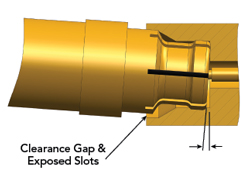
Figure 2 Example of an SMPM socket improperly installed.
The second design constraint for push-on connectors is improper mating. When SMPM connectors are misaligned or tilted during installation, shielding effectiveness is further reduced. Tilting the connectors increases the clearance gap and further exposes the socket slots. Figure 2 shows an improperly installed SMPM socket mated with a smooth bore pin connector.
Interface engagement also impacts connector retention during operation. For the SMPM, the socket’s flexed fingers provide a radial outward force onto the outer conductor of the pin connector, resulting in limited mechanical retention between the mating connectors. To increase retention force, a full detent SMPM pin connector can be used in place of a smooth bore. As implied by its name, a full detent connector has a detent feature within the pin outer conductor that acts as a small mechanical “speed bump.” The detent requires the socket connector to flex inward further than a smooth bore, increasing the retention force and securing the connectors during use. However, the increased mating force also makes installation more challenging.
During system integration, care must be taken to ensure that the socket connector is fully engaged for proper performance. This requirement becomes more challenging as packaging density increases and access is limited. An installer must connect each assembly by hand and ensure proper mating of the connectors without the support of a torque wrench. Improperly installed connectors can result in a discontinuity at the mating interface, resulting in a high impedance that degrades VSWR performance. Misaligned connectors, such as those shown in Figure 2, are also at risk of becoming entirely uninstalled in field use.
Threaded SMPM
The threaded SMPM is an alternative option that reduces the SMPM design constraints with a modest reduction in packaging density. This design is derived from the standard SMPM interface and incorporates a compact coupling nut on the socket connector with external threads on the pin connector. During installation, the socket is mated by hand. The nut is then slid overtop the socket, threaded onto the pin and torqued using a calibrated wrench. The coupling nut provides a standardized engagement force, pulling the socket forward and ensuring the connectors are fully mated.
In addition to mechanical retention, the coupling nut provides an additional ground path between the mating connectors, fully covering the exposed socket slots and improving shielding effectiveness. The consistent engagement force of the threaded SMPM gives system engineers greater confidence that the connectors are fully mated, optimizing VSWR performance and reducing the risk of disengagement in use.
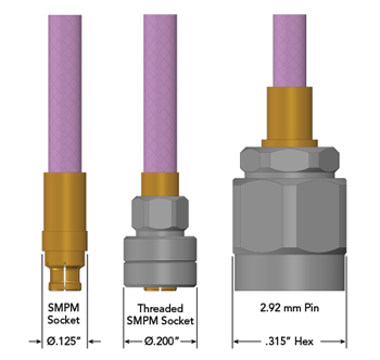
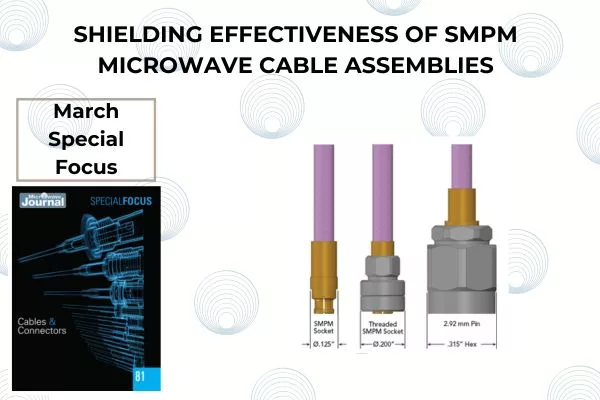
Figure 3 Comparison of a standard SMPM socket connector, threaded SMPM socket and 2.92 mm pin connector.
Figure 3 shows three connectors manufactured by W. L. Gore & Associates, Inc. The standard SMPM socket connector, threaded SMPM socket and 2.92 mm pin connector are shown together with the same scale. The threaded SMPM offers a practical compromise because of the coupling nut’s compact size. The version manufactured by W. L. Gore & Associates, Inc. has a diameter of 0.200 in., giving a 36 percent increase in density compared to the hex of a 2.92 mm connector’s coupling nut.
SHIELDING EFFECTIVENESS OF EW CONNECTORS
Measuring Shielding Effectiveness
The mode-stirred method (ANSI/EIA-364-66B-2025) is used when evaluating the shielding effectiveness of microwave assemblies at RF frequencies. It provides an end-to-end measurement of an assembly’s shielding performance, evaluating the cable, connectors and quality of the connector termination simultaneously. The shielding effectiveness is measured in 1 GHz steps from 1 to 40 GHz.
The dynamic range is the noise floor of the mode-stirred equipment and is a characterization of the equipment’s capabilities. To ensure measurement accuracy, the dynamic range must be at least 10 dB greater than the target value of the sample.2 For microwave assemblies, the MIL-T-81490A requirement is 90 dB. Most mode-stirred chambers have capabilities much greater than that requirement through 18 GHz, with typical dynamic range values near 140 dB at 1 GHz and 110 dB at 18 GHz.
The equipment’s dynamic range is measured after calibration and plotted together with test results to indicate sample quality. If the shielding effectiveness of a sample measures near the dynamic range, it indicates excellent performance.
Shielding Effectiveness of Threaded Connectors
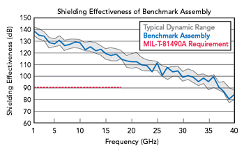
Figure 4 Shielding effectiveness of a benchmark assembly.
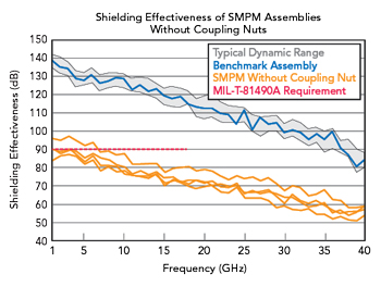
Figure 5 Shielding effectiveness of SMPM assemblies without a coupling nut.
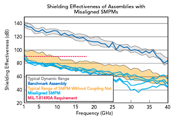
Figure 6 Shielding effectiveness of assemblies with misaligned SMPM connectors.
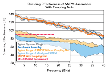
Figure 7 Shielding effectiveness of SMPM assemblies with a coupling nut.
For flexible cables, an outer conductor composed of helically wrapped metal foil gives the best shielding effectiveness. W. L. Gore & Associates, Inc. manufactures microwave cable with a helically wrapped silver-plated copper foil. Wrap designs offer mechanical and electrical contact between the layers, eliminating gaps while maintaining flexibility for installation and routing.6 Pairing this cable with threaded connectors and good solder termination results in excellent shielding effectiveness for the assembly — on par with the typical dynamic range of a mode-stirred chamber.
Figure 4 shows a representative benchmark example of W. L. Gore & Associates, Inc.’s flexible cable terminated with threaded connectors. The gray region in the plot shows the typical dynamic range of the test equipment, calculated from multiple runs over several days. The blue trace shows the shielding effectiveness of the benchmark assembly. The benchmark overlaps the dynamic range through 40 GHz and far exceeds the MIL-T-81490A requirement of 90 dB through 18 GHz, shown by the red dashed line.
Shielding Effectiveness of SMPMs With and Without Coupling Nuts
Threaded SMPM cable assemblies were built using the same type of flexible cable as the benchmark example. These samples were used to evaluate the shielding effectiveness of the SMPM connector with and without a coupling nut. On one end, the assemblies were terminated with a threaded connector and attached to the test equipment. The second end used a threaded SMPM socket connector, which was the connector under evaluation.
The shielding effectiveness of an SMPM interface without a coupling nut was evaluated by mating the socket connector to a pin adapter and leaving the interface exposed. An effort was made to verify the socket connector was fully engaged and not tilted off-axis. The coupling nut was left retracted, away from the mating interface. Representative results of the SMPM without a coupling nut are shown in Figure 5 as orange traces. The typical dynamic range, benchmark assembly and MIL-T-81490A specification are also included for comparison.
The shielding effectiveness of an SMPM connector without a coupling nut is significantly reduced compared to the benchmark across all frequencies. The results fall below the 90 dB requirement by 7 GHz and approach 60 dB by 35 GHz. Depending on the LRU application needs and frequency of operation, this level of performance may require additional consideration by a system designer. Assemblies may need to be spaced further apart, or RF power levels reduced to mitigate EMI concerns.
Another experiment evaluated the performance of improperly mated SMPM connectors. The samples were intentionally tilted within the pin adapter. Again, the coupling nut was left retracted and away from the SMPM interface. This attempted to recreate the situation shown in Figure 2, where the socket connector is incorrectly installed, and there is a gap at the interface between the two connectors.
The shielding effectiveness results of the misaligned samples are plotted in Figure 6 as light blue traces. The typical range of an SMPM connector without a coupling nut, calculated from the previous results, is also plotted as an orange shaded region. The benchmark example, typical dynamic range and MIL-T-81490A specification are also shown for comparison.
The improperly mated SMPMs have reduced shielding effectiveness compared to the properly installed SMPM connectors without a coupling nut. The results of the misaligned samples fall below the 90 dB specification immediately, near 1 to 2 GHz. There is a sharp downward trend, and the traces diverge from the properly mated examples. Around 32 GHz, the performance is at its worst, with values as low as 40 dB. The results are also inconsistent between samples because each connector is uniquely misaligned. This increases the challenge for the system designer, as shielding is not only degraded by misaligned samples but also yields variable, unpredictable results. These examples highlight the importance of ensuring proper installation when using push-on connectors.
Another round of testing measured the shielding effectiveness of the threaded SMPM connector. In this test, the SMPM socket was installed onto a threaded SMPM pin adapter. The coupling nut was engaged and torqued using a calibrated wrench, ensuring the connectors were fully mated.
With the coupling nut engaged, the shielding effectiveness of the threaded SMPM assemblies is excellent. Figure 7 shows representative samples plotted as dark orange traces. Also included are the previous results and MIL-T-81490A specification. The typical range of a misaligned SMPM connector, calculated from previous results, is shown plotted as a light blue shaded region.
The shielding effectiveness of the threaded connectors overlaps the dynamic range at most frequencies and greatly outperforms a standard SMPM without a coupling nut. The performance is on par with the benchmark assembly, offering excellent performance through 40 GHz. The threaded SMPM samples far exceed the MIL-T-81490A requirement with headroom through 18 GHz. This level of shielding indicates the connectors have minimal EMI impact on LRU system performance.
CONCLUSION
Upgraded and new EW systems require higher RF power at higher frequencies within the same LRU footprint or smaller. This combination naturally leads to EMI concerns for microwave assemblies, as they are tightly routed together near subsystem electronics within the LRU.
When choosing microwave connectors, engineers should compare the advantages and limitations of each option. Traditional threaded connectors offer excellent shielding effectiveness but are space-limited by their relatively bulky coupling nuts. Push-on connectors, such as the SMPM, offer the highest density advantage and allow for tight packaging within LRUs. However, they require careful installation to ensure proper mating, and their shielding effectiveness is reduced compared to threaded connectors. The threaded SMPM provides a third alternative, offering excellent shielding effectiveness. The connector’s compact coupling nut delivers significant space savings while providing a locking mechanism between the mating connectors, reducing installation variability and maintaining performance in use. Regardless of the application, proper selection of microwave cable and connectors help maximize system performance.
References
- P. Pino, “Reducing EMI/RFI in Microwave Cable Assemblies for A&D Systems,” Microwave Journal, November 14, 2019, Web: https://www.microwavejournal.com/articles/33098-reducing-emirfi-in-microwave-cable-assemblies-for-ad-systems.
- “ANSI/EIA-364-66B-2025: EMI Shielding Effectiveness Test Procedure for Electrical Connectors,” Electronic Components Industry Association, Revisions B, June 17, 2025, Web: https://store.accuristech.com/standards/ecia-eia-364-66b?product_id=2949540&srsltid=AfmBOoqWYNMnTjhVBFyQnW53qjkgaPSuKrw5WTaWQtnEDaCz9ZEtditI.
- “MIL-T-81490A (AS): Transmission Lines, Transverse Electromagnetic Mode,” Department of Defense, Revision A, April 22, 1991, Web: https://quicksearch.dla.mil/qsSearch.aspx.
- “MIL-STD-348B: Radio Frequency Connector Interfaces,” Department of Defense, Revision B with Change 4, August 12, 2024, Web: https://quicksearch.dla.mil/qsSearch.aspx.
- “IEEE 287.1: IEEE Standard for Precision Coaxial Connectors at RF, Microwave, and Millimeter-Wave Frequencies-Part 1,” IEEE, Revisions 2021, September 16, 2022, Web: https://ieeexplore.ieee.org/document/9889249/versions.
- P. Pino, “Shielding Effectiveness of Microwave Cable Assemblies,” Microwave Journal, March 12, 2018, Web: https://www.microwavejournal.com/articles/29809-shielding-effectiveness-of-microwave-cable-assemblies.