The satellite ground segment market is undergoing significant evolution, driven primarily by the growth of low Earth orbit constellations and high-throughput satellites. As the number of satellites in orbit and the demand for better connectivity continue to increase, there is huge potential, but also a range of challenges and complexities that come with this evolution. The ground segment urgently needs to reinvent itself to keep up with the pace of change.
One area with room for innovation in the ground segment sector is the argument between transceivers and low noise block down-converters (LNB) and block up-converters (BUCs), otherwise known as discreets. For some, satellite transceivers are completely replacing discreets. Other users are more wary of ditching the discreets, fearing loss of flexibility, performance or functionality. This article discusses the key differences and similarities and highlights when users would need one versus the other.
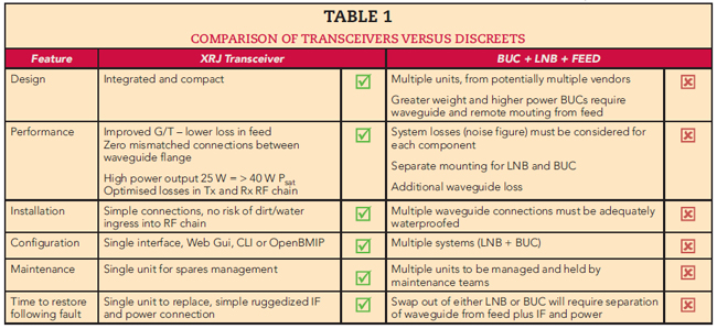
TALKING TO THE SATELLITE: DISCREETS AND TRANSCEIVERS
Satellites operate at extremely high frequencies. For example, Ka-Band operates from 26 to 40 GHz, Ku-Band from 12 to 18 GHz and C-Band from 4 to 8 GHz. This is a stark comparison to most network connectivity equipment, which operates from around 70 MHz to 2.4 GHz. The industry needs a way to up-convert those signals to higher frequencies before transmission to the satellite. Additionally, ground systems must be able to convert incoming signals to the low frequency ranges after reception from the satellite for transmission to the antenna receiver unit. This is vital, as it allows the data to be processed for display on end-user devices.
DISCREETS: SIGNAL CONVERSION
A discreet is the catch-all term for LNB and BUC, integral parts of any satcom system. BUCs convert low frequency signals into high frequency signals that can then be amplified and transmitted to satellites, whereas LNBs are designed to receive sensitive high frequency satellite signals from orbiting satellites and convert them to lower frequencies.
Satellite antennas require both elements to ensure that signals can be converted at both the transmit and receive ends. In this setup, the antenna will have a feed element connected to communicate with the BUC and LNB. In most cases, the feed element will consist of a feed horn, an orthomode transducer (OMT) and a polarizer. These will then be mounted on separate mechanical structures, which must be linked together using cabling and waveguides. As signals pass through these elements, signal loss is possible and must be minimized to avoid connectivity issues. This means both the LNB and the BUC must be close to the feed.
Transceivers: Transmit and Receive
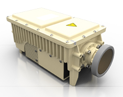
Figure 1 XRJ transceiver from Global Skyware, part of the Global Invacom Group.
Transceivers combine the transmit and receive functions of both LNBs and BUCs along with the feed horn, polarizer and OMT, into a compact single device. A transceiver, such as the multi-orbit XRJ transceiver shown in Figure 1, can be mounted directly on the back of an antenna, with the feed on the other side directly connected to the transceiver. This reduces the amount of waveguide runs and requires only one mechanical structure, rather than three. This also makes for a more straightforward assembly. However, depending on the applications, they may not be a perfect replacement for a system of discreets.
DO TRANSCEIVERS MEAN LESS POWER?
Several arguments have been raised against switching to transceivers, including the risk of reduced power capability. BUCs, in particular, deliver very high power, making them ideal for applications such as broadcasting and telecommunications. While this is true, there is a perception that transceivers can only be low power, making them unsuitable for many applications. This perception is driven by port-to-port isolation within the transceiver. If isolation is poor, the transmitter noise floor desensitizes the receiver and limits data throughput, thereby reducing available power. However, new innovations, better engineering tools and precision fabrication have resulted in transceivers offering greater port-to-port isolation, making them more powerful than ever. This makes them comparable to discreets and powerful enough for most applications. The problem of potential interference between components within the same box requires transceiver manufacturers to both engineer and conduct extensive testing. This is not always to the same level as discreets because the component parts may be different each time. Careful engineering and extensive testing increase customers’ confidence that a transceiver is designed and tested to ensure all components work together seamlessly.
When referring to transceiver power levels, it is often unclear whether specifications are defining saturated or linear power. Linear power (PLin) refers to the ability of an amplifier to increase the power of a signal without distortion. After that point, the signal will be distorted and limit the types of waveforms that can be transmitted to the satellite. Saturated power (PSat) is the maximum power an amplifier can deliver; however, at this level, the signal may be distorted, and data throughput can drop significantly. Often, transceivers are measured using (PLin) because it is a more realistic representation of the actual output achievable without signal distortion. However, many vendors, especially with discreets, will quote the maximum (PSat), which is around twice the (PLin). This can make it unclear and more challenging to compare actual performance.
The Benefits of Integration
One of the most significant differences between the approaches is that transceivers are integrated into existing systems and replace multiple parts, including cabling, while discreets have external cabling. This has several effects on the signal.
Firstly, signals going through additional RF elements connected to the antenna experience more signal losses, as touched on above. In the case of a transceiver, the polarizer, OMT and feed horn are integrated, minimizing losses, whereas these are separate components when using discreets. As the signal passes from one stage to the next, losses will be introduced at each interface. Typically, this introduces a loss of approximately 0.3 dB. This integration reduces this value. Reducing losses and the number of elements the signal passes through will improve both the antenna gain-to-noise temperature ratio (G/T) and effective isotropic radiated power. This ultimately results in better performance.
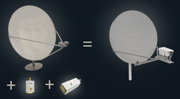
Figure 2 Using a transceiver reduces the physical space required and simplifies cabling and spares.
In addition to simplifying the cabling and spares, using a transceiver dramatically reduces the physical space required, as shown in Figure 2. This is particularly important for comms-on-the-move or other applications where space is a premium. Of course, fewer parts and fewer cables also make setup much easier and more efficient. Again, for comms-on-the-pause applications, especially in a defence setting, being able to set up quickly is an absolute must. In defence, it is not feasible to connect multiple parts, especially if they need to be connected in a specific order, as they will often be set up quickly and in challenging conditions.
Involving fewer components also brings the mean time between failure down. Additionally, in the integrated system, polarity switching is internal and automatic, making it easy to switch to a different frequency band or satellite with lower risk of error.
Another benefit of an integrated system is fewer exposed components. It is well known that RF solutions can be impacted by environmental elements, such as rain, snow, dust or ice. In some cases, this can be immediately detrimental; in others, it can simply shorten the equipment’s lifespan. Therefore, it is valuable to prevent external elements from entering or affecting the electronics.
Flexibility Versus Accountability
Despite the benefits of integrated systems, there are downsides to consider. For example, if something fails, the entire transceiver must be replaced rather than a smaller component. This is the biggest deterrent to the integrated approach; however, it is rare in well-designed, thoroughly tested transceivers.
Furthermore, with discreets, because the parts are separate, users can choose to build the system to their requirements, selecting different vendors for each part and choosing those vendors based on the performance and quality of each individual component. This can provide greater flexibility in purchasing choices; however, it also introduces complexity and may pose interoperability challenges.
The most common scenarios where engineers choose discreets over transceivers are when they require high power. These use cases are limited, but there are key cases, such as transmitting to multiple carriers, where the power is being spread across multiple bandwidths, requiring more total power to distribute over each carrier. In most cases, satellite terminals operate with a single modem and a single carrier, but not always. For example, command posts for networks providing connectivity between teams and back to headquarters become more of a hub than a satellite terminal. This is most common in rapid-deployment scenarios, such as during a disaster. For instance, during a forest fire, teams must be quickly deployed around the affected areas. At the same time, they need to be connected to each other and any centralised operations to share intelligence. Another such scenario might involve a large forward-operating base in the defence sector. There are a couple of ways to handle this, including implementing multiple antenna systems in place, or using a bigger, powerful BUC and integrating multiple carriers.
Using a transceiver integrates multiple complex functions of the RF chain into one product, thereby lowering procurement, testing and assembly costs. The integrated system will have been developed by a single vendor. On the one hand, that removes the flexibility to pick and mix different elements from different vendors. However, on the other hand, that makes a single vendor accountable, simplifying the process of addressing any errors that might arise.
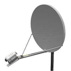
Figure 3 Example of a transceiver.
Transceivers themselves are flexible, allowing for simple and automatic polarity switching as mentioned. This makes it easy to change frequency band, satellite or orbit.
Fighting Gravity
Because discreets have more parts connected to the antenna, they are generally offset from the antenna’s centre. This significantly affects the system’s weight balance. Transceivers are typically mounted on the opposite side to the feed, which keeps them close to the centre and makes the system axis symmetric, as shown in Figure 3. The closer to the centre you can position the RF elements, the less impact of the pull of gravity. In systems where elements are less central and are pulled downward, there is often strain on the motors, which can lead to frequent replacement. Improving the balance of the entire system is therefore likely to make the individual elements more robust and last longer.
Selecting the Right Product for the Application
Ultimately, the choice between transceivers or discreets will come down to a few factors, as shown in Table 1. As mentioned, the power level is a key factor. It may also depend on the existing setup and whether the user needs to replace a single element. However, for new systems, transceivers can deliver enough power to be comparable with discreets in most applications. Transceivers can provide a neat and integrated solution that is easier to set up, is more resistant to the elements and has reduced signal losses due to fewer cables and parts to negotiate.