

THE ROLE OF DRFM IN MODERN ELECTRONIC WARFARE
In the evolving landscape of electronic warfare (EW), digital radio frequency memory (DRFM) systems have emerged as indispensable tools for deception, spoofing and jamming. DRFMs operate by digitizing incoming RF signals, storing them and retransmitting them with precise control over delay, phase and frequency. This process allows DRFMs to effectively manipulate an adversary’s radar through techniques such as false target generation, range gate pull-off, velocity deception and coherent spoofing.
As radar systems become more agile, employing frequency-hopping, pulse compression and complex modulation schemes, the demands on DRFM fidelity and timing precision increase significantly. Testing such systems requires instruments that can match or exceed the signal dynamics of modern radars, such as Rohde & Schwarz’s FSWX.
The FSWX is a high-performance, multi-channel signal and spectrum analyzer designed for demanding applications, including DRFM testing. It provides synchronized, phase-coherent measurement capabilities, enabling engineers to simultaneously analyze the input and output of a DRFM system. FSWX has an analysis bandwidth of up to 8 GHz in single-channel mode, and 4 GHz per channel in dual-channel mode. The multi-channel architecture is crucial, facilitating timing alignment and phase coherence assessment, both critical metrics for evaluating deception effectiveness.
KEY DRFM TESTING PARAMETERS
When thoroughly testing a DRFM, several characteristics are paramount. Test instruments and the accompanying software must provide the tools to accurately assess each of these:
- Amplitude fidelity: Ensuring the retransmitted signal accurately matches the amplitude of the original. Test instruments must have a high dynamic range and accurate power measurements to enable comparisons with high accuracy. This is vital for preventing the deception from being easily identified by the target radar.
- Phase-coherence: Detecting subtle phase shifts that could betray the deception. Instrumentation must provide precise phase measurements and identify even minute discrepancies. Maintaining phase-coherence is essential for convincing deception scenarios.
- Time delay: Measuring the latency introduced by the DRFM. Precise delay measurements are essential for accurate deception timing, particularly in range gate pull-off (RGPO) and Doppler deception.
- Spectral integrity: Evaluating spurious emissions, harmonics and spectral regrowth. Test instruments must provide detailed spectral analysis, ensuring the retransmitted signal does not reveal the presence of a jammer through unwanted emissions.
- Group delay: Analyzing signal delay across frequency, particularly important for compatibility with chirped radar signals. Instrumentation should ensure accurate replication of chirped waveforms.
- Modulation quality: Assessing error vector magnitude (EVM) and I/Q imbalance in modulated signal playback. Signal and spectrum analyzers must be combined with appropriate digital demodulation options to verify the integrity of complex radar signals.
- Spur and intermodulation characterization: Evaluating the signal purity of the DRFM under multi-tone or modulated excitation. Test instruments must provide identification and quantification of the smallest spurious signals and intermodulation products, indicating potential weaknesses in the DRFM’s design.
These capabilities provide a comprehensive view of DRFM behavior, from initial signal reception to final retransmission, ensuring its effectiveness and adherence to performance specifications. The related test solutions would enable engineers to move beyond simple pass/fail criteria to a deep understanding of the DRFM’s strengths and weaknesses. Rohde & Schwarz’s FSWX spectrum and signal analyzer meets these testing capabilities and incorporates a preselection stage to suppress out-of-band interferers.
LEVERAGING SOFTWARE FOR ADVANCED DRFM TESTING
The core capabilities of signal and spectrum analyzers are further enhanced by dedicated software options, enabling in-depth analysis of specific DRFM functions.
Mastering Radar Pulse Deception
Pulse analysis software, such as the KM700 from Rohde & Schwarz, can transform signal and spectrum analyzers into powerful pulsed signal analyzers, vital for evaluating deceptive techniques relying on pulse manipulation. For example, KM700 delivers:
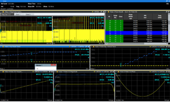
Figure 1 Example of deceptive technique analysis with VSE-K6 pulse analysis.
- Precise pulse parameter measurements: Accurate determination of pulse width, amplitude, rise/fall times, pulse repetition interval (PRI), duty cycle, pulse shape and overshoot. These measurements are foundational for verifying the accurate replication of radar pulse characteristics.
- Advanced pulse train analysis: Examination of pulse repetition frequency (PRF) spectrums, PRI histograms and pulse-to-pulse variations to verify accurate replication of radar pulse sequences and deceptive maneuvers. Analyzing these patterns reveals the DRFM’s ability to convincingly mimic complex radar behaviors.
- Pulse modulation analysis: Support for chirp pulse, pulse width modulation (PWM), pulse position modulation (PPM) and phase modulation analysis, ensuring the DRFM accurately handles complex radar waveforms.
- Advanced triggering: Flexible triggering options based on amplitude, width, PRI and patterns, allowing for focused analysis of specific signals and events within a pulse train.
- Statistical analysis: Providing insights into the consistency and repeatability of DRFM performance across multiple pulses, essential for assessing the reliability of the deception. An example of pulse analysis is shown in Figure 1.
- Segmented capture: Capturing and analyzing long-duration radar signals by dividing them into triggered segments, crucial for complex scenarios and intermittent signals. This feature improves efficiency when analyzing prolonged radar engagements.
SEGMENTED CAPTURE FOR LONG-DURATION TESTING
Software additions can support segmented capture, enabling the analysis of long-duration radar signals by dividing them into individually triggered, time-aligned segments. This functionality is useful in scenarios where radar emissions occur intermittently or when multiple pulse types must be captured across extended periods.
Segmented capture can enable:
- Extended radar scenario coverage: Analyze radar scan patterns or time-varying deception signals.
- Statistical pulse analysis over time: Capture and analyze pulse characteristics across numerous segments.
- Efficient handling of burst radars: Reduce memory consumption by focusing only on signal-rich intervals.
- Detection of rare pulse anomalies: Identify timing irregularities or modulation errors.
By leveraging segmented triggering modes, such as pulse, amplitude or frequency conditions, engineers can perform precise, event-based data acquisition over durations that are not possible with continuous recording methods.
To further support comprehensive radar testing, the FSWX supports segmented capture, enabling analysis of long-duration signals by breaking them into individually triggered, time-aligned segments. With event-based triggering such as pulse detection, amplitude threshold or frequency shift, it captures only meaningful data, improving memory efficiency and analysis focus.
TRANSIENT PULSE ANALYSIS: CAPTURING INTERMITTENT EVENTS
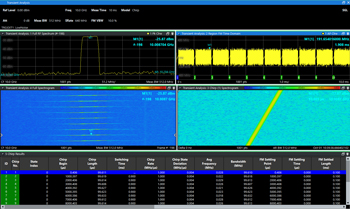
Figure 2 Example of pulse modulation analysis with K710 transient analysis.
Providing both general multi-domain (AM/FM/PM) and spectrogram-based signals, as well as frequency modulated continuous wave (FMCW) demodulation analysis, allows characterization of the capture/replay behavior of the deceptive jammer, as demonstrated in Figure 2. This is crucial for identifying switching transients, spurious artifacts or the fidelity of the replayed scenario introduced during deceptive maneuvers. The FSWX provides these analyses, including these key enabling capabilities:
- Advanced triggering and gating: Pre/post trigger capture and gated analysis allows the isolation of the exact transient of interest (e.g., on-off transitions, memory overwrite events), including amplitude, width, slope and window for capturing specific events, including those with unpredictable timing.
- Time-domain visualization: Features waterfall displays and zoom/pan tools for detailed inspection of transient waveforms, enabling visual identification of subtle anomalies, such as spurious components at switching instants, spectral regrowth, sidebands and other transient events.
- Chirp or hopping measurements: Has a complete capture sequence as well as accurate analysis of one-shot signals, including chirp rate, chirp bandwidth, hop count, hop frequencies and many other parameters providing critical information about transient events of the deceptive maneuver.
PRACTICAL APPS: VALIDATING DECEPTIVE TECHNIQUES
In addition to the basic DRFM testing parameters, specific scenarios require a particular set of capabilities. For example, RGPO validation requires users to precisely measure the PRI shift induced by the DRFM and verify its accuracy. Simultaneously, users monitor any transient signals generated during the PRI shift, indicating potential vulnerabilities. They must ensure the phase relationship between the original and retransmitted signals remains consistent throughout the maneuver. Another scenario to consider is velocity deception validation. Users must analyze the Doppler shift introduced by the DRFM, comparing it to the expected value based on the desired velocity deception. They must also verify that the phase-coherence is maintained throughout the velocity deception, preventing the radar from detecting inconsistencies. Users can perform extended offline analysis using the captured data. An additional scenario is false target generation validation, where users must compare the amplitude, pulse shape, modulation and timing characteristics of the generated false target with those of a real target. They can evaluate the effectiveness of the deception by assessing how convincingly the false target replicates the characteristics of a genuine threat. Finally, a challenging scenario is coherent spoofing analysis, where users verify the phase-coherence between the original and retransmitted signals over extended periods. Even minute phase deviations can reveal deception, so users should watch for performance degradation over time.
ADVANCED ANALYSIS & CHARACTERIZATION

Figure 3 Example of IQ capture spectrum with FSWX.
Signal and spectrum analyzers, including the FSWX, verify that a DRFM can perform a deceptive technique and enable detailed characterization of its performance limits. This includes latency analysis, spectral purity analysis, modulation analysis and occupied bandwidth analysis (OBA). Latency is one of the most critical performance evaluations in DRFM testing. It directly determines how accurately and effectively a DRFM can deceive the victim radar. Precisely measuring the delay introduced by the DRFM at various frequencies and signal levels identifies potential bottlenecks and helps optimize the system for minimal delay. Delays can be caused by A/D and D/A conversion time, digital memory storage and processing, reconstruction and propagation delay through the RF front-end. In a radar and DRFM context, unwanted components such as spurs, harmonics, phase noise, intermodulation products and jitter show that a signal has been improperly reconstructed. Identifying and quantifying spurious emissions and intermodulation products generated by the DRFM minimizes the risk of detection and compromising the jammer. Maintaining the same spectrum content as the radar signal is paramount in ensuring a successful deception campaign. A modern radar waveform is rarely just a simple pulse. It often carries complex modulation, such as linear frequency modulation (chirp or FMCW) and inter-pulse coding with phase-coded sequences (e.g., Barker or polyphase codes). When a DRFM receives and retransmits such signals, it must preserve both the time-domain and modulation fidelity. Any error in modulation reproduction, such as frequency slope distortion in a chirp or phase discontinuities in a coded pulse, can make the spoofed signal look artificial to a radar receiver, rendering the deception ineffective. Evaluating the accuracy of the DRFM’s modulation reproduction ensures that the retransmitted signals maintain the integrity of the original radar waveforms. FSWX supports I/Q analysis with image suppression for improved spectral clarity, as demonstrated in Figure 3. The OBW test ensures that the DRFM output stays within the defined bandwidth limits and does not generate out-of-band emissions that could reveal a spoofing attempt. The OBA measurement ensures that the retransmitted (spoofed) signal maintains the same spectral content, both frequency content and power distribution, as the incoming radar signal. A wider than expected OBW could be an indication of spectral regrowth or unwanted modulation artifacts, as an example. At the same time, a narrower OBW could indicate loss of detail or filtering effects that might make the victim radar lose fidelity in the spoofing signal.
ASSETS FOR DRFM TEST AND VALIDATION
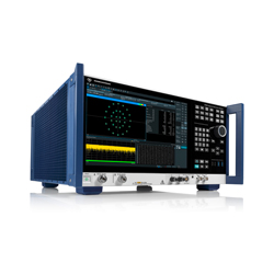
Figure 4 Rohde & Schwarz’s FSWX product.
Signal and spectrum analyzers, such as Rohde & Schwarz’s FSWX, as shown in Figure 4, provide a comprehensive and powerful platform for validating and/or testing next-generation DRFM jammers. From precise parameter measurements to complex deception scenario analysis, these analyzers empower engineers to develop and deploy effective EW systems capable of operating in today’s increasingly complex dense emitter electromagnetic environments. The flexibility, accuracy, multi-channel architecture and advanced analysis tools make the FSWX an indispensable tool for ensuring the superiority of modern electronic warfare capabilities and maintaining a critical advantage during EW missions.
For product details, visit: