
Over-the-air (OTA) testing, once confined to specialist labs, is now the backbone of modern wireless system validation. As 5G, connected vehicles and IoT become everyday realities, the industry’s challenge is no longer just technical — it is pragmatic: deliver reliable system-level validation, keep costs and chamber size down and adapt to new scenarios.
The accelerating evolution of 5G and 6G wireless, coupled with the explosive growth of smarter IoT devices and applications that are now increasingly driven by embedded AI, is fundamentally reshaping both the scope and demands of OTA testing. Where traditional approaches once focused on isolated device evaluation, test technologies must now be developed to assess integrated wireless systems interacting within compact form factors, with real-time adaptation and context-aware intelligence reflecting the complexities of actual deployment environments.
TESTING BEYOND THE ANTENNA AND INTO COMPACT FAR-FIELD
Classic antenna measurements provide part of the story, evaluating radiated performance in isolation. But as radios morph into integrated “black boxes” radiating modulated signals, engineers need OTA methodologies that test the whole transceiver chain, not just for gain and directivity, but for how antenna impedance, hardware coupling and adjacent systems impact real-world connectivity.
Traditional near-field measurement is impractical for such system-level tests, hence the reliance on direct and indirect far-field approaches.1 The rise of 5G, 6G, vehicle-integrated radio systems and electrically larger devices with respect to the wavelength, created a new imperative and drive for innovation: design OTA chambers to be as compact as possible, often by merging multiple functionalities within a single setup to maximize efficiency.
RETHINKING FAR-FIELD DISTANCE: THE EFFD
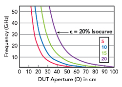
Figure 1 Maximum deviation from EIRP at 3 m.
Here, innovation starts with the question: how close is “far enough” for reliable far-field OTA measurement? The long-held Fraunhofer or Rayleigh distance, dictating huge test chambers, does not fit today’s reality. The introduction of the effective far-field distance (EFFD) approach reshaped best practices. This practical approach enables engineers to select a test range for a desired maximum error.2
The EFFD approach is based on quantifying the maximum allowed deviation, ε, on key metrics such as equivalent isotropic radiated power (EIRP) or antenna gain, as a function of measurement distance “R,” device under test (DUT) size “D” (diameter of the minimum sphere containing the DUT) and frequency “f.” The set of equations published by the IEEE2 establishes the deviation as a predictable function, enabling the design of substantially smaller chambers for controlled accuracy loss. Figure 1 shows the maximum deviation from EIRP at 3 m as a function of DUT size and frequency, showcasing how smaller chambers yield predictable errors.2
For example, instead of an 18 m Fraunhofer-distance based chamber for testing a 30 cm, 30 GHz device, 3 m of range length could be accepted if a 15 percent error can be tolerated. The price to pay for such distance reduction is the inflation of specific uncertainty contributors. Yet coupling a priori knowledge of the DUT with dedicated error compensation algorithms may support the mitigation of such effects. A relevant example is the parallax compensation algorithm, which allows limiting the uncertainty associated with the DUT phase center offset from the center of measurement system coordinates.3
ANTENNA TEST RANGES: SMALLER AND SMARTER
5G’s mainstream adoption sparked the demand for compact antenna test ranges (CATRs), the gold standard for user equipment and base station validation. The ATS1800C CATR, as shown in Figure 2, exemplifies this trend: small enough for a standard doorway (1.53 (L) × 0.90 (W) × 1.99 m (H)), yet able to deliver a 40 cm “quiet zone” meeting 3GPP RF conformance requirements from 6 to 90 GHz for user equipment testing.4 This quiet zone is achieved through a 71 × 69 cm parabolic reflector with rolled edges mounted at the ceiling, offset fed by a corrugated choke horn with an orthomode transducer located at the chamber backwall center (light blue area). The chamber base includes a roll-over-elevation positioner with a maximum accumulated positioning error of 0.1 degree on both axes for an 8 kg DUT.
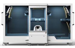
Figure 2 ATS1800C ultra compact CATR (center), with additional side chambers (ATS1800M) for multi-angle-of-arrival tests.
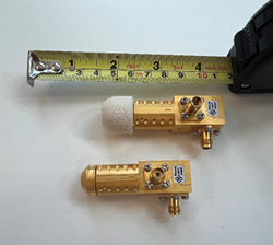
Figure 3 New broadband CATR-FE60B wideband feed.
Reaching a quiet zone of this size in such a tight anechoic chamber required thousands of simulations for a co-optimization of the reflector and feeder system. Some details on the design process are presented by A. Tankielun et al.5, where even further optimization was achieved through a new broadband design CATR feed covering a 3:1 bandwidth (22 to 64 GHz), a 2x to 3x wider frequency coverage than classical feeds (see Figure 3). This CATR-FE60B wideband feed has a high field uniformity variant with a diffusing lens and a low path loss variant without.
Figure 2 also illustrates how the vertical CATR in the center can be complemented with two side chambers, adding three more reflector-feed systems. This unique and patented multi-CATR setup was invented to support 3GPP radio resource management testing with two angles of arrival, supporting all relevant 3GPP mmWave OTA tests in one single anechoic environment. Key design and validation aspects for this setup are detailed by C. Rowell, B. Derat and A. Cardalda-García.6
A “thermal bubble” can surround the DUT, permitting controlled OTA testing at temperatures from -40°C to +85°C, pivotal for automotive, aerospace and industrial applications.4 The description of the design of a thermal testbed for metrology of active antennas outlined by B. L. Schoenholz, J. M. Downey and M. T. Piasecki7 provides insights into how the performance of state-of-the-art mmWave arrays (here for connected objects used in space applications) is critically affected by temperature. In this example, there is more than 4 dB of gain over temperature (G/T) variation across a 60 K range, which must be qualified and potentially compensated in the device.
PLANE-WAVE SYNTHESIS: PRECISION AT THE SMALLEST SPACE COST
Plane-wave synthesis (PWS) prompted another leap forward. This technology uses arrays of controlled sources to create uniform electromagnetic illumination over a “quiet zone” at a fraction of the classic range size. Rohde & Schwarz was the first to bring this methodology to market with the R&S PWC200 test system, shown in Figure 4.
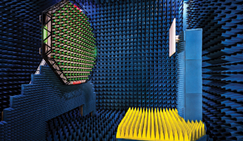
Figure 4 R&S PWC200 PWS system.
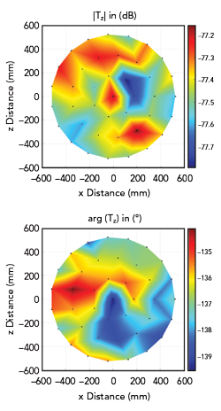
Figure 5 Field magnitude and phase variation in the quiet zone, 1.05 m disc at 2 m and 3.3 GHz.
PWS arrays achieve uniformity by digitally controlling amplitude and phase at each element, synthesizing wave fronts with deviations from an ideal plane-wave with possibly less than ±0.3 dB in amplitude and ±2 degrees in phase across meter-scale zones (see Figure 5). This is particularly advantageous for evaluating large 5G/6G antenna panels employed for massive MIMO.
Detailed studies8 demonstrated quiet zone quality and PWS uncertainty more systematically. They established that PWS systems rival compact ranges in accuracy while reducing spatial footprint by a factor of 2 to 5, depending on the configuration. Indeed, where a CATR requires a reflector twice the quiet zone diameter D at 5 D distance, PWS achieves similar test fidelity at 1.8 D aperture and just 2 D range. The concept’s limitation is bandwidth, typically bound by the capabilities of the beamforming circuitry. Yet, when the frequency range is suitable for the tests, PWS likely provides the most space and cost-effective OTA test alternative, at least in the sub-6 GHz frequency range.
BEYOND MEASUREMENT: AUGMENTED OTA AND DIGITAL TWINS
Some RF performance scenarios are too complex or cost-prohibitive for exhaustive measurement. Here, hybrid approaches, blending measured near-field data and numerical modeling in an augmented OTA approach, are the new standard.9,10
For example, validation of in-vehicle connectivity9 can be solved through spherical scans of the antenna under test, where those measured data are then transformed to numerically “excite” a detailed model (a vehicle interior with passengers, etc.), or true “digital twin” workflow. For 5G/6G vehicular and IoT deployments, digital twin methods offer a crucial pathway to mapping dynamic, real-world scenarios onto repeatable lab procedures. By linking measurement to simulation, engineers can systematically explore device performance over thousands of conditions with statistical rigor and at scales impossible via hardware alone.
Figure 6a shows a car middle console with antennas measured in a spherical scanning OTA range, Figure 6b represents a car model with passengers and Figure 6c displays the calculated in-cabin electric field distribution from measured data injected in IMST EMPIRE XPU simulation software.
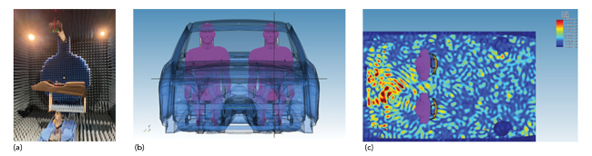
Figure 6 Digital twin workflow with (a) a car console in an OTA range, (b) a car model and (c) calculated in-cabin electric field distribution.
These hybrid techniques also extend to complex exposure evaluations, where absorption rates in the human body are predicted via combined OTA measurements and real computation.10 Recent advances in interfacing measurements and simulations and phase-retrieval of digitally modulated signals with no RF port access make these methods both practical and scalable.11,12
CHARACTERIZING RIS: THE MBET ADVANCE
The future of wireless includes smart, reconfigurable intelligent surfaces (RIS), but their bistatic radar cross section (RCS) evaluation would classically demand complex and costly lab setups. The development of a monostatic-bistatic equivalence theorem (MBET) addressed this: researchers can now transform monostatic CATR measurements into bistatic RCS data with a mean deviation over all angles better than -24 dB, as confirmed experimentally.13
Figure 7 shows RCS data, represented in this case with UV projections for a RIS configured for an incident angle of (EL - 30 degrees, AZ - 45 degrees) reflected towards (EL - 30 degrees, AZ - 285 degrees) at 28 GHz. Figure 7a shows the raw monostatic measurement, Figure 7b shows the simulated bistatic RCS and Figure 7c shows the MBET-reconstructed bistatic RCS.
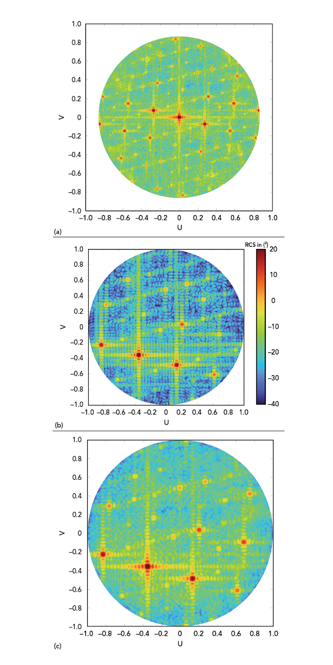
Figure 7 RCS measurements in UV projections for a specific RIS and configuration.
RIS technology is projected as a breakthrough for next-generation network control, spectrum re-use and ultra-low power wireless design. By enabling space-efficient and accurate lab-based RCS validation, the MBET technique could be key to unlocking testing capabilities for scaling up RIS deployment.
THE ROAD AHEAD FOR OTA: DIGITAL TWINS AND INSTRUMENTATION TECHNOLOGY
With fresh insight into far-field boundaries, continued refinement of compact ranges and PWS chambers and the rise of numerically augmented OTA, the wireless industry stands ready for rapid transformation. The next frontier could be the deeper integration of experimental measurement and simulation, moving OTA facilities toward true digital twin validation. Measurement will create and tune the digital twin, while simulation will open nearly unlimited possibilities for realistic and complex scenario testing.
On the instrumentation side, advancements are equally crucial. As the latest RF analyzers and calibration techniques become available, OTA measurement delivers more precise, complete results. Recent work, for example, on enhanced group delay measurements on devices with embedded mixers using a harmonic phase reference and two-step calibration14 highlights just one example of how much progress is possible.
As 5G matures and 6G and IoT move from vision to reality, the sophistication and scale of required test solutions will only grow. The convergence of cutting-edge hardware and simulation tools promises a future where this scale can be reached, no challenge is too complex and no OTA test scenario is out of reach.
Acknowledgments
Special thanks to the unwavering engineering teams at Rohde & Schwarz, IMST GmbH and Prof. Keusgen at TU Berlin.
References
- B. Derat, C. Rowell and A. Tankielun, “Promises of Near-Field Software and Hardware Transformations for 5G OTA,” IEEE Conf. on Antenna Meas. & Applications (CAMA), 2018, pp. 1–4.
- “Discussion on Measurement Test Distance for Determining EIRP or TRP for Active Antenna Systems,” IEEE SA, White Paper, ANSI C63, 31 Jan. 2024.
- G. F. Hamberger et al., “Correction of Over-the-Air Transmit and Receive Wireless Device Performance Errors Due to Displaced Antenna Positions in the Measurement Coordinate System,” IEEE Trans. on Antennas and Propag., Vol. 68, No. 11, 2020.
- B. Derat et al., “Acceleration of Over-The-Air Measurements Under Extreme Temperature Conditions Through Optimization of Air Flow and Thermal Efficiency,” Antenna Meas. Tech. Asso. Symp. (AMTA), 2022.
- A. Tankielun et al., “A Novel Wide-Beam Broadband Feed Enabling Ultra-Compact Antenna Test Ranges,” Antenna Meas. Tech. Asso. Symp. (AMTA), 2025.
- C. Rowell, B. Derat and A. Cardalda-García, “Multiple CATR Reflector System for Multiple Angles of Arrival Measurements of 5G Millimeter Wave Devices,” IEEE Access, Vol. 8, 2020.
- B. L. Schoenholz, J. M. Downey and M. T. Piasecki, “Design of a Thermal Testbed for Metrology of Active Antennas,” 2022 Antenna Measurement Techniques Association Symposium (AMTA), 2022.
- A. Tankielun et al., “Quiet Zone Verification of Plane Wave Synthesizer Using Polar Near-Field Scanner,” 14th European Conf. on Antennas and Propag. (EuCAP), 2020.
- B. Derat et al., “Optimization of In-Vehicle Connectivity through Simulation-Augmented Antenna Measurements,” Antenna Meas. Tech. Asso. Symp. (AMTA), 2022.
- B. Derat et al., “Absorbed Power Density Assessment Using Simulation-Augmented Over-the-Air Measurement,” IEEE Access, 2024.
- D. Schaefer et al., “Power Normalization for Over-The-Air Augmented Exposure Assessment,” German Microwave Conf. (GeMIC), 2024.
- B. Derat, M. Erkocevic and G. Hamberger, “Reconstruction of Near-Field Millimeter-Wave Power Density from Over-The-Air Measurements,” IEEE Conf. on Antenna Meas. & Applications (CAMA), 2021.
- F. Bette et al., “Monostatic to Bistatic Equivalence Theorem for 2-Dimensional Reflection Pattern Measurements of Reconfigurable Intelligent Surfaces,” Antenna Meas. Tech. Asso. Symp. (AMTA), 2025.
- B. Derat et al., “Over-The-Air Group Delay Measurements of Frequency-Converting Devices Using a Harmonic Phase Reference,” Antenna Meas. Tech. Asso. Symp. (AMTA), 2025.