

Power sensors, such as LadyBug’s LBSF09A compact RF power sensor, are widely used in manufacturing test systems across industries, including communications equipment, RF component validation, printed circuit board testing, military and aviation hardware, wearables and medical devices.
These cost-effective tools allow manufacturers to verify product performance either directly or within a test chamber, ensuring compliance and quality. Power sensors add value throughout the manufacturing process; by identifying defective subassemblies or components before integration, they prevent inventory build-up of faulty parts and reduce wasted time and resources.
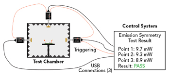
Figure 1 Test chamber with a DUT and three power sensors equipped with antennas.
Figure 1 depicts a test chamber with three power sensors connected to a test system. The three power sensors are connected by USB-C connections and linked with daisy-chained triggering, allowing the test system to synchronize and evaluate all measurements simultaneously. During testing, the device under test (DUT) can be rotated inside the chamber, enabling the collection of comprehensive RF radiation data.
With their frequency coverage, accuracy and measurement flexibility, power sensors are well-suited for testing devices that incorporate new signal formats, high-power components or emerging technologies. Integrated into automated test equipment (ATE), they deliver rapid analysis during early manufacturing stages and after final assembly. This allows engineers to devote more effort to product design and process optimization.
FROM TRADITIONAL TEST SYSTEMS TO MODERN SENSORS
Test equipment has evolved over the past several decades. Early systems relied on bulky power meters paired with external sensors and required frequent manual calibration steps, such as zeroing and input isolation. These procedures often interrupted the test process and slowed throughput.
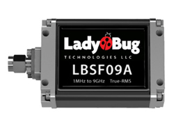
Figure 2 LadyBug LBSF09A RF power sensor.
Modern power sensors, by contrast, are compact, self-contained instruments with interfaces such as USB, HiSLIP LAN, SPI and I2C. LadyBug’s patented NoZero technology eliminates re-zeroing, ensuring uninterrupted operation. The result is faster, more reliable testing with higher overall efficiency, see Figure 2.
APPLICATION EXAMPLE: DEVELOPMENT TO PRODUCTION
In early product development and initial manufacturing runs, companies often build small-scale test systems tailored to their specific device. These setups allow engineers to validate performance, explore design tradeoffs and confirm regulatory compliance before investing in large-scale automated equipment.
Compact USB or LAN-connected power sensors are particularly valuable at this stage. They integrate with laboratory PCs, require minimal support hardware and can be controlled through common software environments such as Python, MATLAB or LabVIEW. This flexibility reduces setup time and keeps development costs low.
When a product succeeds in the market and production volumes increase, testing requirements evolve from small, single-station setups to fully integrated production test systems. Power sensors support this transition by enabling engineers to establish validated measurement routines during early development and then carry those same routines into scaled manufacturing. This continuity ensures consistent results across stages, minimizes re-engineering efforts and accelerates the path from product concept to high volume deployment.
TECHNICAL EXAMPLE: MEASURING RETURN LOSS
Return loss (RL) is a common parameter used to verify device performance. Figure 3 shows a compact test setup using two LadyBug LBSF09A 9 GHz power sensors and directional couplers. A signal source drives the DUT, while one sensor measures forward power and the other measures reflected power.
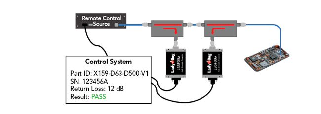
Figure 3 Example simple system for automated return loss measurement.
To minimize measurement uncertainty, the coupler monitoring reflected power is placed closest to the DUT. This placement improves directivity (forward/reverse isolation), reducing error across all power levels. At very low signal levels, where noise dominates, the sensor’s dynamic range, exceeding 86 dB, enables detection of small reflections.
Formula and Calculation
RL is defined in Equation 1 as:
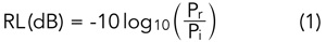
where:
- Pi = incident (forward) power into the DUT
- Pr = reflected power from the DUT
Power values are measured in linear units (e.g., mW) and then converted to decibels. Since the ratio is dimensionless, any consistent linear unit can be used. In practice, engineers often prefer to work directly in dB for convenience, but the underlying calculations are performed in the linear domain to maintain accuracy.
Correction Factor
To account for coupler loss and coupling factors, a tracking correction factor T is applied, as shown in Equation 2:
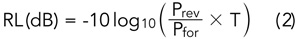
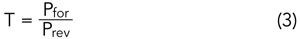
A typical method for determining T is to measure with a known full reflection (shorted port), as demonstrated in Equation 3:
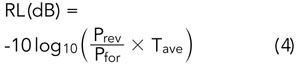
For higher accuracy, measurements are taken with both open and short terminations. Averaging these results yields a correction factor, Tave, which removes most system source match errors. This correction factor is then applied in the RL calculation in Equation 4:
Practical Considerations
The system can automatically detect conditions such as reflected power near the noise floor, indicating insufficient signal, unexpected RL values, DUT faults, DUT mismatches, measurement inconsistencies due to component defects or poor connections. By logging and flagging such events, defective devices can be identified before they enter final assembly or shipment, improving yield and reducing costs.
While RL can also be measured with a one-port network analyzer, such instruments are more expensive and less flexible than a power-sensor-based setup. In a manufacturing line, multiple RL measurements are often required at different assembly stages or test stations. Outfitting each point with a network analyzer would be cost-prohibitive, whereas deploying additional power sensors is both practical and economical. This makes power-sensor-based systems attractive for scalable manufacturing, where accuracy, throughput and cost control are all critical.
Note on VSWR
Some engineers prefer to express a mismatch in terms of voltage standing wave ratio (VSWR). VSWR can be derived directly from RL using the relationships in Equations 5 and 6:
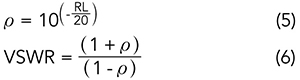
Only the magnitude of the reflection is measured (ρ = |S11|). Phase information is not measured and is not required for the RL or VSWR calculations. This approach allows automated test systems to report both RL and VSWR at each station without additional hardware or measurements.
BROADER APPLICATIONS
While RL is a representative example, power sensors also support compliance testing, EMC assessments, calibration of other RF equipment and verification of production test systems. Their cost-effectiveness and interoperability make them suitable for a wide range of manufacturing environments.
SOFTWARE AND INTERFACE INTEGRATION
Modern manufacturing test systems are no longer isolated benches with a few dedicated instruments. Instead, they are complex networks of sensors, sources, controllers and databases, all coordinated by software. Power sensors fit into this environment because they provide standardized communication protocols and flexible connectivity options.
STANDARDIZED COMMAND AND CONTROL
LadyBug LBSF and LB5900 series power sensors support the standard commands for programmable instruments (SCPI) protocol, a widely adopted standard defined by IEEE 488.2. SCPI enables consistent control and data acquisition across different programming environments, including Python, C, C++, C#, MATLAB and LabVIEW. This interoperability ensures that engineers can integrate power sensors into almost any automated test framework without the need for specialized drivers.
For example, in Python, engineers can communicate with sensors over USB or LAN using libraries such as pyvisa, sending SCPI commands to configure measurements, retrieve power levels and log results. In larger test environments, virtual instrument software architecture abstracts the hardware connection so that the same code can operate over USB in the lab or LAN in production without modification.
Multi-Sensor Coordination
A key advantage of compact power sensors is their ability to operate in parallel. A single PC or industrial controller can manage multiple sensors simultaneously, each addressing a different test point or station. This scalability is key in manufacturing, where several measurements must be taken at different points along an assembly line. Coordinating multiple sensors through a centralized control program provides synchronized data collection and simplifies pass/fail decisions.
Data Management and Traceability
In modern factories, measurement results are rarely used only for real-time verification. Instead, they are stored in databases, linked to product or subassembly identification numbers and analyzed for trends. Power sensors can stream results directly into manufacturing execution systems or statistical process control software.
Remote and Distributed Testing
Remote Interfaces extend the reach of power sensors beyond the local workstation. This allows test stations to be monitored remotely or aggregated across multiple production sites. In some deployments, data is collected and analyzed in near real-time at a central location, providing global oversight of distributed manufacturing lines. USB, meanwhile, remains valuable for single-station setups where simplicity and low cost are paramount.
NEXT-GENERATION TEST SYSTEMS
The increasing complexity of RF products and the rising demand for higher throughput are reshaping the design of automated test systems. While today’s power sensors integrate seamlessly with software frameworks and production databases, the next generation of systems may extend this integration further — leveraging Industry 4.0 concepts, cloud connectivity and advanced data analytics where appropriate.
In many deployments, measurement data may not remain confined to the local test station. Instead, results can be aggregated in centralized or cloud-based platforms, where advanced statistical methods and machine learning may be applied to identify subtle shifts in device performance before they cause yield degradation. This predictive capability gives manufacturers the option to act proactively, whether by adjusting processes, recalibrating equipment or isolating component lots.
Similarly, power measurements are increasingly being used as active triggers in automated workflows. Depending on system design, they can initiate equipment calibration, quality alerts or supply chain adjustments in real-time. Interfaces such as LAN, HiSLIP, SPI and I2C provide the flexibility to embed sensors into both legacy systems and emerging IoT-enabled architectures.
Together, these trends suggest the direction of next-generation test systems: distributed, data-driven and highly adaptive. Within this framework, compact and thermally stable power sensors are well-positioned to remain a key enabler of future test systems, delivering accuracy, scalability and cost-effectiveness while supporting the transition to future manufacturing models.
CONCLUSION
Power sensors have become indispensable in modern manufacturing test systems. They offer lower cost and reduced complexity compared to other options, scalability to integrate at every stage of assembly verification and flexibility through multiple interfaces and standardized SCPI commands. As assemblies grow more compact and complex, the role of power sensors will continue to expand. Their accuracy, adaptability and seamless software integration make them a cornerstone of next-generation ATE.