
From a designer’s perspective, it may be acceptable to use a capacitor above the SRF if the application requires low impedance with no requirement for the capacitor to exhibit either capacitive or inductive behavior. However, as the operating frequency approaches the first PRF, the designer must decide if the higher loss is acceptable for the application. If the loss is too high, an alternative solution may be necessary. Therefore, from a design standpoint, it is critical to determine if any PRFs fall within the intended operating frequency range. As shown, Modelithics Microwave Global Models for MLCCs enable the identification of PRFs to mmWave frequencies.
HOW CASE SIZES IMPACT CAPACITOR RESONANCES
Several factors impact capacitor resonances. One such factor is the case size of the MLCC. Figure 5 shows an impedance simulation of the Microwave Global Models for the KEMET CBR02, CBR04 and CBR06 capacitors, which come in case sizes of 0201, 0402 and 0603, respectively. Each simulation uses a capacitor model with a value of 33 pF. The substrate used for each is 10 mil thick Rogers RO4350B.
For the CBR02, CBR04 and CBR06 capacitors with the same value (33 pF), the SRFs are 1.568 GHz, 1.132 GHz and 968.3 MHz, respectively. Therefore, increasing the case size increases the ESL and thus decreases the SRF. The impedance value at the SRF corresponds to a capacitor’s ESR. For the CBR02, CBR04 and CBR06 capacitors, the ESR values are 98, 77 and 62 mΩ, respectively. Thus, by increasing the case size, the ESR decreases.
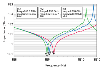
Figure 5 Simulated impedance curves of the CBR02 (red trace), CBR04 (blue trace) and CBR06 (green trace) capacitors.
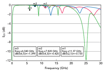
Figure 6 Simulated S21 of the CBR02 (red trace), CBR04 (blue trace) and CBR06 (green trace) capacitors.
Simulating the same three capacitor models in a two-port series configuration shows that the PRFs are affected by case size. Each model is set to a value of 6.8 pF. The substrate used for each is again 10 mil thick Rogers RO4350B. Figure 6 shows the simulated S21 of each capacitor.
For the CBR02, CBR04 and CBR06 capacitors with the same value, the first PRFs are 11.37, 7.82 and 6.04 GHz, respectively. Again, the PRFs decrease as the case size increases. From a design perspective, this comparison highlights the suitability of these capacitors for applications such as DC blocking. That is, the 6.8 pF CBR06 capacitor would likely not be an appropriate choice for an application if the operating passband includes the capacitor’s first PRF of 6.04 GHz. In comparison to the 6.8 pF CBR06 capacitor, the 6.8 pF CBR02 capacitor would be a candidate for use in more broadband applications because it exhibits a first PRF at a much higher frequency (11.37 GHz).
SUBSTRATE AND SOLDER-PAD EFFECTS
The substrate on which an MLCC is mounted also affects the resonances. The substrate affects the parasitic elements of an MLCC and thus impacts the locations of the resonant frequencies. Simulating the Microwave Global Model for the Amotech A60F capacitor series demonstrates this impact. The model uses a value of 27 pF using two different substrates: 10 mil thick Rogers R04350B and 60 mil thick Rogers RO4003C. For both cases, the simulation includes the impedance and the S21 (two-port series configuration).
Figure 7a shows the simulated impedance curves for both substrates. The 10 mil thick Rogers RO4350B substrate produces an SRF of 1.252 GHz, whereas the 60 mil thick Rogers RO4003C substrate produces a lower SRF of 792.1 MHz. This illustrates that increasing the substrate thickness results in a lower SRF.
Figure 7b shows the simulated S21 for both cases. The results show steeper attenuation notches at the PRFs when using the 60 mil thick Rogers RO4003C substrate versus the 10 mil thick Rogers RO4350B substrate. Modelithics’ capability to predict substrate-dependent performance is a key program feature.
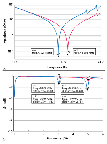
Figure 7 (a) Simulated impedance with 10 mil (red trace) and 60 mil (blue trace) substrates. (b) Simulated S21 with 10 mil (red trace) and 60 mil (blue trace) substrates.
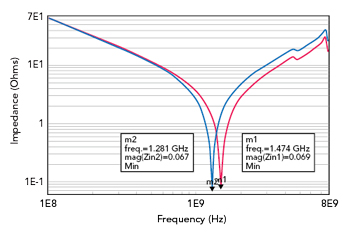
Figure 8 Simulated impedance with pad lengths of 17 mils (red trace) and 28 mils (blue trace).
In addition to the substrate, the SRF is affected by the dimensions of the solder pads on which an MLCC sits. Microwave Global Models scale with respect to the solder-pad dimensions. This pad scalability makes it possible to see how the SRF changes as the pad dimensions are varied. Analyzing the Microwave Global Model for the Amotech A60L capacitor series demonstrates the scalability. In this example, the value is 24 pF, and the capacitor models have two different pad lengths: 17 and 28 mils. For both cases, the pad width and pad gap are set to 20 mils each. The substrate used is 10 mil thick Rogers RO4350B. Figure 8 shows the simulated impedance for both cases. Increasing the length of the solder pads from 17 to 28 mils results in a decrease in the SRF from 1.474 to 1.281 GHz. These results are expected since increasing the length of the solder pads increases the inductance and thus lowers the SRF.
MLCC HORIZONTAL AND VERTICAL MOUNTING ORIENTATIONS
It is possible to eliminate odd-order parallel resonances by mounting an MLCC in a vertical orientation. Mounting an MLCC in a vertical orientation means that the width of the MLCC essentially becomes its height. Figure 9 shows an MLCC mounted on a PCB in both horizontal (Figure 9a) and vertical (Figure 9b) orientations. While horizontal orientation is often considered the default mounting configuration, vertical orientation can be employed to eliminate odd-order parallel resonances.
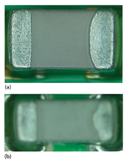
Figure 9 MLCC in both (a) horizontal and (b) vertical orientations.
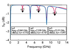
Figure 10 Simulated S21 for the A60F 27-pF “Horizontal” (red trace) and “Vertical” (blue trace) modes.
Many of Modelithics’ Microwave Global Models for MLCCs include an “Orientation” parameter that lets users select either “Horizontal” or “Vertical” mode. This parameter allows designers to predict the behavior of an MLCC when mounted in both horizontal and vertical orientations. Figure 10 shows S-parameter (S21) simulations of the Amotech A60F 27 pF capacitor in a two-port series configuration using both “Horizontal” and “Vertical” modes. For this analysis, the substrate used is 30 mil thick Rogers RO4350B. The first-, third- and fifth-order PRFs (3.06, 7.03 and 11.01 GHz, respectively) only appear when the model is set to “Horizontal” mode. When the model is set to “Vertical” mode, these odd-order parallel resonances are eliminated.
FINAL REMARKS
Modelithics’ Microwave Global Models for capacitors enable designers to determine where resonances, including SRFs and PRFs of an MLCC, appear. The resonances depend on factors such as case sizes, substrates and solder-pad dimensions. Using these inputs, the designers can determine the best capacitor for the application.
References
- 1. Johanson Technology, “SRF & PRF AND THEIR RELATION TO RF CAPACITOR APPLICATIONS,” Tech Note.
- KYOCERA AVX, “Circuit Designer’s Notebook.”