

Over-the-horizon high frequency surface wave radars (HFSWRs) are appearing along the coast of the People’s Republic of China and in their artificial islands in the South China Sea. As the technology is seen to fruition as part of an integrated anti-access/area denial (A2AD) scheme, these radars will be capable of detecting and tracking ships well beyond 300 km, aircraft above and below the horizon, ballistic missiles and cruise missiles, with near-targeting quality azimuth and range accuracy. Robust countermeasures are needed, as they have the capability to detect and track “stealth” platforms due to the long high frequency (HF) wavelengths.
INTRODUCTION TO HFSWR
Due to the conductivity of salt water, a vertically polarized wave in the HF, 3 to 30 MHz domain will propagate along the curvature of the ocean for hundreds of kilometers without relying on an ionospheric bounce. The U.S.’ HFSWR experiments provided proof of concept in the 1960s and 1970s at the Naval Research Laboratory led by James Headrick, and in the 1970s with the U.S. Air Force-sponsored TOP SEA radar developed by Leon Lewandowski and colleagues at Sanders Associates (now BAE Systems). Canada and other nations have advanced the state of the art to operational systems for over-the-horizon 200 NM Exclusive Economic Zone (EEZ) ship surveillance. China’s interest in HFSWR also began in the 1960s. HFSWR installations are inherently large compared to microwave radars due to the long wavelength and need for a large receiving aperture for bearing accuracy. The open literature on the subject is substantial, as is worldwide academic, civilian and military interest for applications ranging from hydrography to EEZ enforcement to low-altitude over-the-horizon cruise missile detection and tracking.

Figure 1 A conceptual shipboard HFSWR, optimized for ASCM detection.1

Figure 2 Russian Podsolnukh HFSWR antennas.
Surface wave propagation is lossy compared to line of sight (LOS), but excellent performance can be achieved even with the inherent difficulties of operation in the HF band. Ship detection is best in the lower HF band; higher frequencies are better for aircraft and missiles. A system intended primarily for early warning of incoming sea-skimming anti-ship cruise missiles (ASCM) might be optimized around 15 to 20 MHz. To illustrate the over-the-horizon concept and performance, a relatively small conceptual shipboard system,1 sponsored by the U.S. Navy, operating in the 10 to 18 MHz range can achieve useful tracking ranges from an aperture length of less than 185 m, as illustrated in Figure 1. Larger coastal installations will achieve much longer ranges. In contrast, the enormous 1500 m Russian coastal surveillance Podsolnukh HFSWR, as shown in Figure 2, tracks targets out to 500 km and has reportedly been exported to China.2,3
HFSWR COMPLEXITIES AND ADVANCES
Advances in digital receivers over the last approximately 30 years have enabled the development of practical systems. Beamforming, target detection and tracking can all be done digitally with minimal operator involvement. Modern digital receivers in the HF band feature analog to digital converters and low phase noise, which enable high sub-clutter visibility necessary for detecting slow-moving targets at extended ranges. Unlike HF over-the-horizon backscatter (OTH-B) radars, sounders are not needed because HFSWR does not depend on the ionosphere. However, many of the challenges, such as external noise, man-made interference and the need for high sub-clutter visibility, are shared between these two distinct types of HF radars. HFSWR performance is different from microwave radar due, in part, to three key factors:
1. Receive array directivity: Directivity rather than gain is often used for the receiving system because it is dominated by the external noise level rather than internal thermal noise. HF is almost always externally noise-limited, often by over 40 dB.
2. Surface wave propagation loss: Surface wave propagation loss is an additional loss that can be substantial and poses a significant challenge to the radar designer. Two-way loss varies by frequency and sea state; path loss over 200 dB is typical for long-range ship detection at the low end of the HF band and increases with frequency.
3. External noise: External noise is naturally occurring in the HF band and is much higher than internal kTB noise. Typically accepted planning values are 50 dB above kTB at 2 MHz, reducing to 20 dB at 30 MHz. When man-made interference is added, depending on location, time of day, etc., values of 80 dB have been observed at the low end of the band.

Figure 3 Maerospace dual-band HFSWR product performance. Source: Maerospace Corporation.
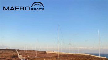
Figure 4 Maerospace HFSWR installation, Cape Race, Newfoundland. Source: Maerospace Corporation.
Canada is a leader in EEZ ship monitoring using HFSWR. Maerospace, based in Ontario, Canada, has developed a fourth-generation HFSWR with 120-degree azimuthal coverage up to 200 nm. Their radar — Persistent Active Surveillance of the EEZ (PASE) — operates from 3 to 5 MHz and is approximately 650 m in length. They own and operate one of their radars, as demonstrated in Figures 3 and 4, on the East Coast of Canada, in Newfoundland. Maerospace’s HFSWR product is representative of the state of the technology readily available today.
The dual-use military potential of commercially-available HFSWR systems cannot be overlooked. The constraints on the HFSWR radar designer are substantial. Nikolic, et al.4 describes a Serbian development of a frequency modulated continuous wave (FMCW) HFSWR for EEZ monitoring in the Gulf of Guinea and elaborates on some of the constraints they faced for this EEZ single-purpose system. It also provides excellent diagrams of a semi-bistatic EEZ ship monitoring shore-based design and likely ship detection ranges.
Since 1967, China has developed HFSWRs,5 which have been deployed at multiple sites along its coast. Open literature suggests that HFSWR is part of their overall integrated A2AD scheme. Chinese academic literature on the subject is substantive and demonstrates a long-term commitment to advancing this technology. They are building HFSWR systems in the South China Sea within the disputed Spratly Islands, including on Cuarteron Reef, as shown in Figure 5.6 The reef is claimed by China, Taiwan, Vietnam and the Philippines.
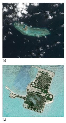
Figure 5 Chinese HFSWR site on disputed Cuarteron Reef in the South China Sea.
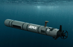
Figure 6 HII REMUS can deliver electronic warfare payloads.

Figure 7 Boeing EA-18G Growler electronic warfare aircraft.
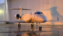
Figure 8 BAE Systems/L3-Harris Compass Call.
A key advantage of operating in the HF band is that target scattering is typically in the Rayleigh and Mie (resonance) regions because the wavelength of the radar is larger or nearly equal to the target of interest. Reducing radar cross section (stealth) via shaping and radar absorbing materials becomes less effective, making HFSWR an attractive means of beyond the horizon A2AD coastal surveillance.
HFSWR systems are monostatic, semi-bistatic or truly bistatic. Monostatic systems will be the most compact and are likely modulated high-duty-cycle pulsed systems consistent with their range and Doppler resolution requirements. The operating frequency range can vary from as low as a few MHz to as high as 18 to 25 MHz, depending on the target of interest and on noise and interference conditions. Once a target breaks the radar horizon, such as a high altitude aircraft or a ballistic missile, LOS propagation comes into play and detection ranges increase accordingly. Antenna choices vary with the design; a notional multi-purpose military system might include a log-periodic monopole transmitter serving as a wide-beam illuminator and multi-frequency digital receive array configurations covering a wide HF spectrum to detect a carrier strike group at a great distance, detect and track aircraft as they are launched and detect and track cruise missiles beyond the horizon to provide early cueing of engagement systems.
HFSWR challenges must be emphasized before considering countermeasures. Foremost, surface wave over-the-horizon propagation is lossy when compared to LOS propagation, an inherent opportunity for the ECM designer to exploit. Sea clutter moving in Doppler, target to clutter ratio, sea state, external noise, man-made interference (e.g., shortwave radio) and other factors will degrade detection range. The requirement for meaningful near-targeting quality range and Doppler information will limit waveform choices. Bearing accuracy is almost entirely a function of receive array size. HFSWR systems must have high sub-clutter visibility to detect moving targets in the presence of moving ocean clutter. A modern HFSWR is likely to place a high dynamic range digital receiver at every antenna element, to the degree affordable, for simultaneous digital beamforming to match the coverage of the transmit antenna, and adaptive nulling of interference (e.g. shortwave radio transmitters) and directional jamming. Frequency agility or multiple simultaneous frequencies can optimize target detection, so a multi-purpose system might be either operating in three simultaneous bands or shifting between those bands. Choosing frequencies within each band may be based on finding the quietest parts of the HF spectrum or pseudo-random to make jamming more difficult, or a combination thereof. A coherent integration time interval is needed to pull moving targets out of the ocean clutter. The clutter patch is moving, and ocean currents and sea state influence detection and false alarm rates; constant false alarm rate (CFAR) processing and target tracking are non-trivial problems for the HF radar designer.
CONSIDERATIONS FOR COUNTERMEASURES DESIGNERS
Target processing and waveform optimization literature speak volumes for three intelligence needs: a constant OSINT effort, frequent ELINT collection and analysis of signals of interest and theoretical analysis of likely wartime modes. Given the complexities of operating a radar at HF, the different optimal frequencies as a function of target size, external noise, clutter and interference, frequent collection is required to build a strong understanding of how these systems operate over time and electromagnetic conditions. HF radar experts in the U.S., Canada and Australia can provide the knowledge to assist the ECM designer in understanding how these radars operate now and how they might operate in wartime and the future. The good news for the ECM designer is that the radar designers are under constraints that are perhaps more challenging than those of their microwave counterparts due to the HF electromagnetic environment and surface wave propagation loss.
A small team of HFSWR radar experts, talented ECM designers, HF equipment designers, A2AD experts and those skilled in modern autonomous payload delivery methods such as unmanned underwater vehicles (UUVs), unmanned surface vehicles (USVs), etc., if provided with visionary leadership that invites creativity, can quickly converge on a variety of flexible yet affordable solutions. With a long duration and range, and a modular payload capability, the HII REMUS autonomous underwater vehicle, as shown in Figure 6, is one potential delivery example; multiple units can operate collaboratively, which may enable new countermeasure ideas.
The first consideration for the ECM designer is that of mission. Since the sites are relatively large, perhaps relocatable but not immediately mobile, and their locations fixed by imagery and HFDF, destruction of enemy air defenses (DEAD) using conventionally guided weapons is an option. Given the large site, how many weapons are required to take it down and how long will it take an adversary to reconstitute the site with spare equipment? Equipment shelters for transmitters and receivers can be hardened or underground, and the operators need not be on site.
Early warning radars are ideal candidates for denial and tactical deception rather than destruction. Causing an adversary to make bad decisions might be better than simply blinding their sensor. The degree to which this is possible against HFSWR needs analysis, but history suggests there may be several things that could be done to degrade and deceive.
Another consideration for the ECM designer is partial or full digital adaptive beamforming. A digitally beamformed HF radar may have many degrees of spatial freedom, but some will be needed to null directional interference, such as skywave noise and narrowband communications overlapping with the wideband radar waveform. Digital beamforming is a potential ECCM feature, but also a vulnerability since an affordable HFSWR site may only have 32 receivers at any given time. This might imply jamming close to the radar using multiple sources over a wide angular sector, which provides significant transmit power (J/S) advantages given the higher loss of surface wave two-way propagation.
Airborne jamming from the EA-18G Growler (see Figure 7) or EA-37B Compass Call (see Figure 8) is challenging due to the HF antenna size when the wavelength of operation is measured in tens of meters. Clever antenna designers have created retractable, long wire, electrically small and efficient airborne HF antennas, but these are often tuned for a particular band. High altitude HFSWR jammers would have a distinct propagation advantage when above the LOS radio horizon, so there is a tradeoff to be considered.
Shipboard HF systems are likely to be adaptable to this mission, providing screening jamming for themselves and the carrier strike group, but this requires radiation from the ships, which are often in emission control (EMCON). Offboard, non-collocated jammers well in front of the strike group may make more sense and provide a significant jam-to-signal ratio (J/S) advantage. The emergence of highly capable UUVs and USVs makes this a more practical option than in the past.
ECM techniques to be considered range from simple noise to high-fidelity false targets. The high two-way path loss and the unique HF environment, and thus complex radar CFAR detection, might make for interesting twists on ECM techniques, especially if delivered much closer to the radar than the assets under protection. Overcoming adaptive beamforming will be a challenge, but understanding the actual available spatial degrees of freedom and the likely radar signal processing methodology may yield insights leading to highly flexible ECM techniques used in sequence or in combination to defeat or deceive. Jammers do not need to be overly complex and may not require high transmit power to be effective. As with other modern battlefield “throw-away” items, modern HF software-defined digital transceivers may enable simple devices in larger quantities that may be more effective than a few expensive assets.
Getting the jammer closer to the threat relative to the assets being protected appears to be an attractive approach. Close is relative, given the long ranges and lossy two-way propagation to the distant asset being protected. Close-in might be measured in 10s of kilometers, and the jammers are hidden under a vast ocean, popping up an antenna when jamming is needed. A field of these jammers may be sufficient to overwhelm the radar’s digital beamforming at an affordable cost relative to the assets, such as a carrier strike group and its aircraft.
CONCLUSION
High frequency surface wave radar technology is mature and available. HFSWR poses an early warning and target acquisition threat, and countermeasures must be available to the warfighter. HFSWR countermeasures should not just be examined in isolation. The adversary’s overall ISR CONOPs and capabilities must be considered in totality to establish the counter-ISR approach and coordinated electronic and DEAD strategy. Having a full understanding of HFSWR operation and its overall place in the hostile A2AD system is but one part of the puzzle.
Acknowledgments
Scott Marks of Aerospace BD for his assistance in understanding the challenges of operating in the HF band.
Myles Murphy of Aerospace BD for his assistance in assessing the threat.
Jeff Hassannia, David Markman and Nicole Hassannia of Aerospace BD for their material support and encouragement to write this paper. http://www.aerospacebd.com.
Dr. Samantha L. Powers of George Mason University for editing for comprehension.
Leon Lewandowski of Sanders Associates for his unhesitant knowledge transfer and mentoring.
Brian Franklin, VP of Engineering and CTO of Maerospace Corporation for information on their PASE HFSWR product.
REFERENCES
- R. L. Powers, L. M. Lewandowski and R. J. Dinger, “High Frequency Surface Wave Radar,” Sea Technology, Vol. 37, June 1997, pp. 32–40.
- “Russian Podsolnukh,” Global Security.Org, Web: https://www.globalsecurity.org/wmd/world/russia/podsolnukh.htm.
- R. Uppal, “High Frequency Surface Wave Radars (HFSWR) for Ship Detection and Tracking Far Beyond the Horizon,” International Defense Security and Technology, July 29, 2021, Web: https://idstch.com/security/high-frequency-surface-wave-radars-hfswr-for-ship-detection-and-tracking-far-beyond-the-horizon.
- D. Nikolic, N. Stojkovic, P. Petrovic, N. Tošic, N. Lekic, Z. Stankovic and N. Doncov, “The High Frequency Surface Wave Radar Solution for Vessel Tracking Beyond the Horizon,” Facta Universitatis Series: Electronics and Energetics, Vol. 33, No. 1, March 2020, pp. 37–59, Web: https://www.researchgate.net/publication/339253979_The_high_frequency_surface_wave_radar_solution_for_vessel_tracking_beyond_the_horizon.
- “Over-The-Horizon Surface Wave Radar (HFSWR),” Global Security.Org, Web: https://www.globalsecurity.org/wmd/world/china/oth-swr.htm.
- K. Mizokami, “China’s Putting Anti-Stealth Radar in the South China Sea,” Popular Mechanics, February 24, 2016, Web: https://www.popularmechanics.com/military/weapons/news/a19602/china-installing-anti-stealth-radar-in-south-china-sea.