
Magnetic resonance imaging (MRI) has become an indispensable tool in modern medical diagnostics, providing detailed images of the internal structures of the body without the need for invasive procedures. Figure 1 shows an example of the technology with a robotic-assisted MRI surgical station. The technology behind MRI systems is complex and relies on various components to function effectively. One such critical component is the PIN diode. This article delves into the applications and uses of PIN diodes in MRI devices and their broader impact on the medical market.
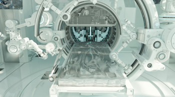
Figure 1 Robotic-assisted MRI surgical station.

Figure 2 PIN diode chip.
UNDERSTANDING PIN DIODES
A PIN diode is a semiconductor device consisting of three layers: a p-type (P) layer, an undoped intrinsic (I) layer and an n-type (N) layer. The intrinsic layer, sandwiched between the p-type and n-type layers, sets PIN diodes apart from other types of diodes. When a PIN diode is forward-biased, a positive voltage is applied to the p-type layer with respect to the n-type layer. When this bias exceeds the PIN diode’s threshold voltage, holes and electrons are injected into the I-region. These charge carriers will recombine, but as the forward-bias voltage increases, the magnitude of these injected charge carriers will overwhelm the recombination process. This establishes a current flow through the device, lowering the resistivity of the intrinsic region and the PIN diode becomes a small resistance. Conversely, when the voltage on the n-type layer of the junction is higher than the voltage on the p-type layer, the PIN diode is reverse-biased. In this condition, free charge carriers are swept out of the intrinsic region and the reactance of the diode becomes quite large. This reverse-biased reactance is determined by the capacitance and parallel resistance of the PIN diode structure. This unique structure allows PIN diodes to operate efficiently at high frequencies and handle significant power levels, making them ideal for various applications, including those in MRI systems. Figure 2 shows a simple PIN diode chip diagram.
APPLICATIONS FOR MRI SYSTEMS
The RF power supply frequency of an MRI machine depends on the strength of the magnetic field used for the scan and can be calculated according to the Larmor frequency. The Larmor frequency, named after Joseph Larmor, is the frequency at which the magnetic moment of a proton, electron or nucleus precesses around a magnetic field. This is the essential phenomenon leveraged by nuclear magnetic resonance and MRI technology. This is fundamental to the operation of MRI as it governs the frequency of oscillation of hydrogen nuclei (protons) in the human body when subjected to high magnetic fields. The Larmor frequency is given by Equation 1:

Where:
ω0 = Larmor frequency
γ = the gyromagnetic ratio of the proton, which is approximately 42.58 MHz/T
B0 = strength of the external magnetic field applied in Tesla (T) units.
Therefore, from Equation 1, a 1.5 T machine would have a Larmor frequency of 42.58 MHz/T × 1.5 T or 63.87 MHz.
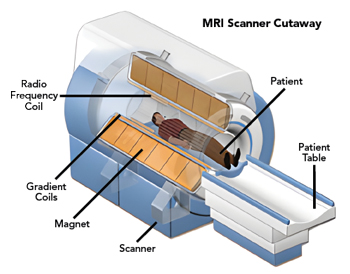
Figure 3 MRI scanner cutaway.

Figure 4 Commercial MRI machine installation.
One of the primary applications of PIN diodes in MRI systems is for RF switching and attenuation. MRI machines use RF pulses to excite hydrogen nuclei in the body, which then emit signals that are detected and used to create images. PIN diodes are employed to switch these RF signals on and off rapidly and to control their amplitude. Their ability to handle high power and operate at high frequencies makes them particularly well-suited for this purpose.
In MRI systems, the same RF coil is often used for both transmitting the RF pulses and receiving the emitted signals. PIN diodes play a crucial role in transmit/receive (Tx/Rx) switches, which alternate between the transmit and receive modes. When the system is in transmit mode, the PIN diode allows the RF pulse to be sent to the coil. Conversely, when the system switches to receive mode, the PIN diode isolates the receiver from the transmitter, thereby preventing damage to the sensitive receiver components.
Modern MRI systems often employ phased array coils, which are composed of multiple smaller coils arranged in an array. These coils can be individually controlled to enhance image quality and reduce scan times. PIN diodes play a crucial role in these coils, enabling the switching of individual elements on and off. This precise control of the RF fields significantly improves the overall performance of the MRI system. RF coils function as resonant circuits tuned to the resonance frequency of proton spins within a given magnetic field. During a scan, RF pulses and magnetic gradients are applied and RF energy is exchanged with the patient to generate images.
The quality of MRI images is heavily dependent on the homogeneity of the magnetic field within the imaging volume. PIN diodes are used in shim coils, which are auxiliary coils designed to correct inhomogeneities in the magnetic field. By adjusting the current in these shim coils, the magnetic field can be made more uniform, resulting in clearer and more accurate images. Figure 3 shows a cutaway of an MRI scanner that illustrates some of these functions and Figure 4 shows a commercial MRI machine installation.
ADVANTAGES IN THE MEDICAL MARKET
The use of PIN diodes in MRI systems offers several advantages that extend to the broader medical market. One of the most significant benefits is their high speed switching capability. PIN diodes can switch on and off very rapidly, which is essential for the fast-paced operation of MRI systems. This high speed switching ensures that the RF pulses are delivered and received with precise timing, leading to high-quality images that are crucial for accurate diagnosis.
Another advantage is the high power handling capability of PIN diodes. MRI systems require components that can manage high levels of power without degrading performance. PIN diodes are well-suited for this task, as they can operate efficiently at high power levels, ensuring the reliability and longevity of the MRI system. This reliability is particularly important in the medical market, where equipment downtime can have serious implications for patient care.
The intrinsic layer in PIN diodes helps to minimize signal distortion, which is crucial for maintaining the integrity of the RF signals used in MRI. Low distortion ensures that the images produced are accurate and free from artifacts, which is essential for effective diagnosis and treatment planning. This level of accuracy and reliability makes PIN diodes an invaluable component in the medical market, where precision is paramount.

Figure 5 Typical packaged PIN diode construction.
Furthermore, the versatility of PIN diodes allows them to be used in various parts of the MRI system, from RF switching to magnetic field correction. This versatility makes them an essential component in the design and operation of MRI machines. These characteristics make PIN diodes invaluable contributors to the advancement of MRI technology and, by extension, the medical market. Figure 5 shows a PIN diode diagram like that of Figure 2. However, in this case, the PIN diode is shown in an axial-leaded package with the anode and cathode connections identified. This points to the packaging flexibility of PIN diodes.
NON-MAGNETIC PACKAGING
The use of non-magnetic packaging for PIN diodes is essential when these components are deployed in environments with high magnetic field strength. Magnetic materials can compromise the performance and reliability of diodes. Non-magnetic materials ensure that the diodes operate correctly without interference from surrounding magnetic fields. This is particularly critical in applications such as medical imaging equipment, scientific instruments and specific communication systems. Employing non-magnetic packaging preserves the integrity and efficiency of PIN diodes, resulting in more accurate and dependable performance in high magnetic field conditions.
MMSM NON-MAGNETIC PACKAGING
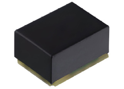
Figure 6 PIN diode in MMSM package.
Monolithic microwave surface-mount (MMSM) packaged non-magnetic diodes are engineered for direct mounting onto printed circuit boards (PCBs), offering several key advantages. Their non-magnetic nature makes them ideal for applications where minimizing magnetic interference is critical, such as in medical imaging equipment, precision instrumentation and aerospace technology. The MMSM packaging significantly reduces the physical footprint of the diodes on the PCB, which is advantageous for modern electronic devices that require compact and lightweight designs. Additionally, surface-mount technology (SMT) streamlines the manufacturing process by enabling automated placement and soldering of components onto the PCB, thereby increasing production speed and consistency while reducing human error. This combination of smaller component sizes and automated assembly processes enables lower production costs through reduced material usage and faster assembly times. By eliminating magnetic materials, these diodes help maintain the integrity and accuracy of sensitive systems, which is crucial in applications where magnetic fields can interfere with electronic circuits. Furthermore, MMSM-packaged diodes are designed to withstand the rigors of modern electronic environments, ensuring long-term reliability and durability even in challenging conditions. Overall, MMSM-packaged non-magnetic diodes leverage SMT to provide significant benefits in terms of space efficiency, manufacturability, cost reduction, performance and reliability, making them an ideal choice for a wide range of high-precision and space-constrained applications. Figure 6 shows a PIN diode in a non-magnetic package.
FUTURE MARKET TRENDS
Recent advancements in neurological imaging are being driven by several key trends, notably the development of 7T MRI machines. These high-field MRI systems are breaking new ground in the diagnosis and study of neurological conditions such as Parkinson’s disease. The increased magnetic field strength of 7T machines offers significantly higher resolution images compared to the more commonly used 1.5T and 3T MRI systems. This enhanced imaging capability allows for more detailed visualization of brain structures and abnormalities, which is crucial for early diagnosis and treatment planning in neurological disorders.
Typical peak RF powers for 1.5T MRI machines generally range from 10 to 15 kW. The required power is determined by a complex calculation that depends on several factors, including the body tissue being imaged, the type of coils in use, whether the coils are configured in series or parallel and the total magnetic power. For a 3T system, the power requirement can exceed 30 kW. With the advent of 7T systems and experimental 10T and 11T systems, the total RF power required can approach 70 to 80 kW. The RF power amplifier technologies used in these RF supply subsystems can be selected from various options, including VDMOS, LDMOS and GaN. Despite the availability of high-power individual transistors, these systems often need to combine the power of 30 to 100 transistors to achieve the necessary total peak output power for the MRI machine.
7T machines are also being used for improved imaging, especially in the emerging segment of MR-guided surgery. These high-field MRI systems are particularly beneficial for detailed imaging of knees and other specific body parts. Moreover, they are becoming increasingly important in the growing field of MR-guided surgery, where precise imaging is crucial for successful surgical outcomes.
There is a fair amount of frequency and application diversity in the MRI industry, in addition to field strength. Whole-body MRI systems operating up to 7 T can have RF signals up to 300 MHz. Head-only MRI systems operating at these same field strength levels up to 7 T or greater use RF signals that can be up to 400 MHz. Many of the lower signal strength 3T MRI systems operate at a 127.74 MHz frequency range, while some of these 3T MRI systems operate at 123.2 MHz, which means they are slightly lower in terms of magnetic strength.
Another important trend in the MRI industry is the shift toward helium-free or reduced-helium MRI machines. Helium is traditionally used as a cryogenic coolant for the superconducting magnets in MRI systems. However, helium is both expensive and increasingly scarce, a situation exacerbated by geopolitical factors such as the Russia-Ukraine war. The scarcity and high cost of helium have driven the demand for new MRI machines that use significantly less helium or eliminate the need for it.
This shift not only addresses the supply chain challenges associated with helium but also reduces the operational costs and environmental impact of MRI systems. As a result, there is a growing market for these advanced machines, leading to the replacement of older 1.5T systems with more efficient and sustainable alternatives. These trends underscore the ongoing transformation in the MRI industry, driven by technological innovation and changing market demands. While these developments do not directly impact the use and value of PIN diodes, they do reflect the growing need for new and advanced MRI machines, which in turn influences the overall market landscape.
CONCLUSION
PIN diodes play a vital role in the functionality and efficiency of MRI systems. Their applications in RF switching, Tx/Rx switches, phased array coils and magnetic field homogeneity contribute to the high-quality imaging capabilities of modern MRI machines. The advantages of high speed switching, high power handling, low distortion and versatility make PIN diodes an essential component in the advancement of MRI technology and the broader medical market. As MRI technology continues to evolve, the importance of PIN diodes in enhancing image quality and diagnostic accuracy will only grow, further solidifying their place in the field of medical imaging.