

Mismatch attenuators were tested by using the multiline TRL, SOLT, LRRM and eSOLR calibration methods. Magnitude and phase results for S21 are shown in Figure 6a and Figure 6b, respectively. As can be seen from Figure 6a, the measured S21 magnitude results using SOLT, LRRM and eSOLR calibration methods are close but somewhat different from those of the multiline TRL calibration method due to the imperfection of the single-port load model used. In Figure 6b, the results for the phase of S21 using the four calibration methods were consistent, with the eSOLR calibration method agreeing better with the multiline TRL calibration method.
New SOLT Calibration Method Using 10-term Error Model
Based on the 16-term error model, the new SOLT calibration method that uses a 10-term error model12 deletes the crosstalk errors e30 and e03 from the VNA receiver and the receiver-to-probe port errors e20, e31, e02 and e13. By removing these six crosstalk errors, the error term has been reduced from 16 to 10 so that the calibration can be done using the same calibration standards as the SOLT calibration method, i.e., short, open, load and through. Figure 7 shows a comparison of the results measured with a 10 dB attenuator calibrated with different methods. In addition, the simulation results are given as a reference value in Figure 7. The figure shows that the measurement results of the new SOLT calibration method using the 10-term error model are closer to the simulation results and smoother as frequency increases, indicating that the crosstalk correction has achieved the desired result.
Calibration-on-the-Fly Method
The calibration-on-the-fly calibration method13 is based on the traditional 8-term error model and four crosstalk error terms are extended based on the 8-term error model. Since the crosstalk occurs between two probe heads, the four error terms that are extended can be thought of as a virtual two-port device connected in parallel with the DUT between the two probe heads. This two-port device has distinct S-parameters, so the electromagnetic wave transmission in this virtual two-port device is related to the reflection of its DUT, which is different from the traditional 16-term error model, treating the crosstalk term as a constant. The 12-term error model with a crosstalk term is shown in Figure 8, where the S-parameter of the virtual two-port device is denoted as SCT.
Figure 9 shows the comparison between the calibration-on-the-fly method and the traditional SOLT, 16-term calibration at 10 dB. The measurement results at 180 GHz are not much different. As the frequency increases, the measured value of S21 using the calibration-on-the-fly method is significantly lower than that of the SOLT calibration method. The S21 measurement results are about one dB lower than those of traditional SOLT measurement results at 220 GHz and are closer to the simulation results. The calibration-on-the-fly calibration method affects the correction of crosstalk progression.

Figure 9 Comparison of the measurement results with different calibration methods.
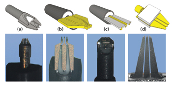
Figure 10 Probes using different processes.
DOMESTIC AND INTERNATIONAL TRENDS FOR PROBES AND CALIBRATION STANDARDS
Before 2020, most of the probes and on-wafer calibration standards came from the U.S., Japan and Taiwan. Probes from FormFactor and GGB in the U.S. reached an upper frequency of 1.1 THz and they had several different form factors. Figure 10a shows micro-coaxial probes from GGB. Figure 10b shows air coplanar probes (ACP) from FormFactor. Figure 10c shows MEMS Z-probes from FormFactor and Figure 10d shows thin-film Infinity probes from FormFactor.
Since 2022, the Chinese mainland has developed and refined the ACP microwave probe process. Companies such as the 13th Research Institute of China Electronics Technology Group Corporation (CETC-13) have developed a 110 GHz microwave probe based on this process with performance comparable to the best available from other countries. The probe products launched in China reach 110 GHz. As semiconductor chips are required at higher frequencies, microwave probes will also be developed to operate at higher test frequencies and provide a longer service life.
As an example of these development activities, a team at Ohio State University in the U.S. used new non-contact measurement probe technology14 to achieve 140 to 220 GHz passive mmWave wafer characterization measurement. This non-contact probe measurement method enables fast, repeatable, low-cost and wear-free evaluation of microwave, mmWave and terahertz integrated circuits. This new method accommodates a wide frequency range from mmWave to terahertz (60 GHz to 3 THz). A team from the University of Virginia in the U.S. used a silicon-based insulator process to fabricate a micromechanical process probe15 that can scale to terahertz frequencies. At present, this kind of micromachined coplanar waveguide probe has been used in the WR-1.0 band (0.75 to 1.1 THz) to realize wafer measurement of coplanar devices. This technology may also be applied to higher test frequencies in the future.
Commercially available on-wafer calibration parts, also known as impedance standard substrates (ISS), are typically made of ceramic substrates. At present, the applicable frequency range of commercial wafer calibration parts outside China reaches 325 GHz. For higher frequency on-wafer measurement requirements, special on-wafer calibration parts need to be made on the tested wafer.16 At the same time as the launch of microwave probes in China, various commercial on-wafer calibration parts were launched, with a frequency covering 110 GHz. At present, CETC-13 is competitive with the best performance for probe resistance change on its commercial calibration standards.
METROLOGY IN CHINA
Since 2012, CETC-13 has completed a number of research programs addressing topics like MMIC automatic test systems, on-wafer S-parameters, load-pull and noise parameters. They are also responsible for compiling several calibration specifications for on-wafer measurements and probe stations. CETC-13 has established the unique CNAS (China National Accreditation Standard) calibration capability for on-wafer S-parameters, on-wafer load-pull and noise test systems in China.
Organized by the State Administration for Market Regulation in 2022, CETC-13 led the national measurement comparison program of on-wafer S-parameters. According to the measurement comparison, on-wafer S-parameter measurements for the joined laboratory were verified, the accuracy and reliability of the transmission of on-wafer S-parameter measurements were ensured, and more relevantly, the main sources of uncertainty in the measurement of on-wafer S-parameters were unified. At the same time, the measurement comparison program also provides the industry with a comparison platform for the consistency of on-wafer S-parameter measurement.
CONCLUSION
This article has reviewed the current development of on-wafer S-parameter calibration methods from RF to terahertz frequency ranges, microwave probes, on-wafer calibration standards and the construction of on-wafer metrology in China. After years of catching up, China has reached a new level in this area. However, for the terahertz frequency band, there is still a gap between China and the rest of the world in terms of microwave probes, on-wafer calibration standards and metrology technologies.
References
- D. F. Williams, F.J. Schmückle, R. Doerner, et al., “Crosstalk Corrections for Coplanar-waveguide Scattering Parameter Calibrations,” IEEE Transactions on Microwave Theory and Techniques, Vol. 62, No. 8, 2014, pp. 1748–1761.
- D. F. Williams, C. M. Wang and U. Arz. “An Optimal Multiline TRL Calibration Algorithm,” IEEE MTT-S International Microwave Symposium Digest, 2003.
- J. V. Butler, D. K. Rytting, M. F. Iskander, et al., “16-term Error Model and Calibration Procedure for On-wafer Network Analysis Measurements,” IEEE Transactions on Microwave Theory and Techniques, Vol. 39, No. 12, 1991, pp. 2211–2217.
- X. Shang, et al., “Some Recent Advances in Measurements at Millimeter-Wave and Terahertz Frequencies: Advances in High Frequency Measurements,” IEEE Microwave Magazine, Vol. 25, No. 1, 2024, pp. 58–71.
- X. Shang, et al., “Interlaboratory Investigation of On-wafer S-parameter Measurements from 110 GHz to 1.1 THz,” 53rd European Microwave Conference, 2023.
- J. Fitzpatrick, “Error Models for Systems Measurement,” Microwave Journal, Vol. 21, No. 5, 1978, pp. 63–66.
- A. Ferraro, “Two-port Network Analyzer Calibration Using an Unknown ‘Thru’,” IEEE Microwave and Guided Wave Letters, Vol. 2, No. 12, 1992, pp. 505–507.
- A. Davidson, K. Jones and E. Strid, “LRM and LRRM Calibrations with Automatic Determination of Load Inductance,” 36th ARFTG Conference Digest, 1990.
- G. F. Engen and C. A. Hoer, “Thru-Reflect-line: An Improved Technique For Calibrating The Dual Six-Port Automatic Network Analyzer,” IEEE Transactions on Microwave Theory and Techniques, Vol. 27, No. 12, 1979, pp. 987–993.
- B. Marks, “A Multiline Method of Network Analyzer Calibration,” IEEE Transactions on Microwave Theory and Techniques, Vol. 39, No. 7, 1991, pp. 1205–1215.
- A. Wu, Y. W. Yehuo, et al., “An Enhanced SOLR Calibration Method,” Acta Metrologica Sinica, Vol. 43, No. 8, 2022, pp. 973–978.
- C. Liu, A. Wu, C. Li, et al., “A New SOLT Calibration Method for Leaky On-Wafer Measurements Using a 10-Term Error Model,” IEEE Transactions on Microwave Theory and Techniques, Vol. 66, No. 8, pp. 3894–3900.
- A. Wu, et al., “Calibration on the Fly—A Novel Two-Port S-Parameter Measurement Method for On-Wafer Leaky Systems,” IEEE Transactions on Microwave Theory and Techniques, Vol. 68, 8, 2020, pp. 3558–3564.
- K. Sertel, “Automated Performance of On-Wafer Calibration and Characterization Using Non-Contact Probes,” 92nd ARFTG Microwave Measurement Conference, 2019.
- M. F. Bauwens, N. Alijabbari, A. W. Lichtenberger, et al., “A 1.1 THz Micromachined On-wafer Probe,” IEEE MTT-S International Microwave Symposium, 2014.
- Y. Wang, et al., “An Advanced Calibration Method for Probe Leakage Correction in On-Wafer Test Systems,” IEEE Transactions on Microwave Theory and Techniques, Vol. 71, No. 2, 2023, pp. 682–690.